
A slag water waste heat heat exchange device for online backwashing

A technology for heat exchange devices and backwashing, which is applied in the direction of cleaning heat transfer devices, flushing, and heat exchange equipment. It can solve the problems of anti-blocking effect, unsatisfactory heat exchange efficiency, and inability to perform automatic backwashing to achieve efficient heat recovery. Energy saving, heat transfer effect and heat exchange efficiency enhancement, novel and unique effect

Active Publication Date: 2017-01-11
四平市中亚热工环保设备制造有限公司
View PDF17 Cites 1 Cited by
  • Summary
  • Abstract
  • Description
  • Claims
  • Application Information

AI Technical Summary

Problems solved by technology

[0003] The purpose of the present invention is to provide a slag water waste heat exchange device for online backwashing, mainly to solve the problems existing in the existing slag water heat exchange device that the backwashing cannot be performed automatically while the device is exchanging heat, and the anti-blocking effect and exchange rate The problem of unsatisfactory thermal efficiency

Method used


Image

  • A slag water waste heat heat exchange device for online backwashing
  • A slag water waste heat heat exchange device for online backwashing
  • A slag water waste heat heat exchange device for online backwashing

Examples


Embodiment Construction

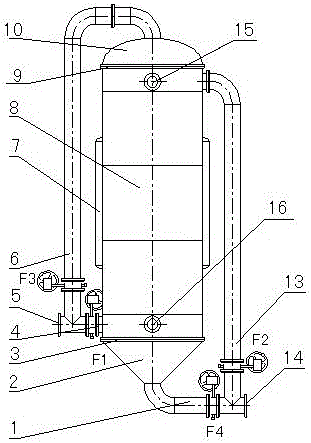
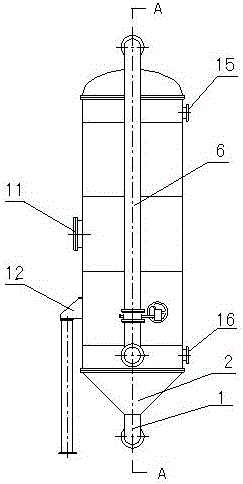
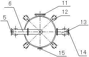
[0018] Depend on figure 1 — Figure 10 The slag water waste heat heat exchange device for online backwashing shown is a new type of heat exchange equipment that effectively utilizes the waste heat of blast furnace slag flushing water for heat exchange. Its middle part is the main body 8 of the slag water heat exchanger. Inside the main body of the heat exchanger 8 are two upper and lower four-channel spiral heat exchange cores, 17, 21, and the spiral heat exchange cores 17, 21 are connected through the semicircular diversion water boxes 7 on both sides of the shell. . Simultaneously communicate with circulating water inlet and outlet connecting pipes 16 and 15 respectively. The top of the main body 8 of the slag-water heat exchanger is connected to the elliptical head 10 through a detachable flange bolt combination 9; the bottom is connected to the conical head 2 through a detachable flange bolt combination 3; the outside is provided with a manhole for easy observation 11 a...


PUM


Abstract

The invention discloses an on-line back flushing residue water afterheat heat exchange device in the field of a heat exchanger. A residue water heat exchanger main body consists of an upper spiral heat exchange core body and a lower spiral heat exchange core body; a residue water main inlet pipe is connected to a residue water inlet pipe through a valve F1; the residue water main inlet pipe is connected with an elliptical seal head through a valve F3 and a back flushing inlet pipe connected with the residue water main inlet pipe; meanwhile, a valve F4 is arranged between a back flushing outlet pipe and a residue water main outlet pipe; a valve F2 is arranged between the residue water main outlet pipe and a residue water outlet pipe; and a residue water filter and a residue water expansion device arranged at the bottom of the residue water filter are arranged at a lower inlet of a residue water passage of a residue water inlet. The on-line back flushing of the heat exchange device can be realized, and the mutual back flushing between the back flushing and the normal heat exchange can be realized. The on-line back flushing residue water afterheat heat exchange device has the advantages that the conception is novel and unique; the structural design is compact and reasonable; anti-blocking and wear-resistant effects are achieved; the service life is prolonged; the heat exchange efficiency is obviously improved; the work performance is stable and reliable; the assembling, the disassembling, the cleaning and the maintenance are convenient; a better humanized effect is achieved; the operation is easy; the heat recovering efficiency is high; energy is saved; and the on-line back flushing residue water afterheat heat exchange device is suitable to be widely popularized in industry, and the like.

Description

technical field [0001] The invention relates to a heat exchange device, in particular to a heat exchange device which is composed of a spiral plate heat exchanger and can perform backwashing automatically while exchanging heat. Background technique [0002] In the production process of the iron and steel industry, the ironmaking blast furnace smelts a furnace of iron every 30 to 40 minutes. The molten iron enters the ladle, and the slag is washed and cooled by the slag water in the slag water pool, and the slag water returns to the slag water pool. The slag contains a lot of heat. The temperature of the pool is also relatively high, generally around 85°C in summer and 75-80°C in winter. If the heat is not recovered in time, it will all be lost to the atmosphere, and the water in the slag pool will evaporate naturally. This not only causes a large amount of heat loss, but also brings about a waste of water resources. However, the blast furnace slag water is characterized by ...

Claims


Application Information

Patent Timeline
Patent Type & Authority Patents(China)
IPC IPC(8): F28D7/02F28F19/01F28G9/00
Inventor 杨光伟刘权田忠
Owner 四平市中亚热工环保设备制造有限公司
Learn More