Two-degree-of-freedom motion decoupling flexible hinge mechanism

A technology of flexible hinges and degrees of freedom, applied in the direction of generators/motors, piezoelectric effect/electrostrictive or magnetostrictive motors, electrical components, etc., can solve the difficulty of increasing the processing and assembly of mechanisms, and the decoupling performance is difficult to achieve Requirements, increase the quality of moving parts of the mechanism, etc., to achieve the effect of compact structure, large bending stiffness, and improved motion accuracy

Inactive Publication Date: 2017-11-14
TSINGHUA UNIV
View PDF5 Cites 0 Cited by
  • Summary
  • Abstract
  • Description
  • Claims
  • Application Information

AI Technical Summary

Problems solved by technology

In the parallel flexible hinge mechanism, there are two forms of space and planar parallel flexible hinge mechanism. Since the control of the flexible hinge mechanism requires the use of two-dimensional and three-dimensional flexible hinges, the processing is difficult and the accuracy is difficult to guarantee. Therefore, the planar flexible hinge mechanism is currently used more. hinge mechanism
[0004] Realizing the motion decoupling of the flexible hinge micro-motion mechanism is the focus and difficulty in the design of this type of mechanism. The current method is to add a decoupling structure, but the existing decoupling structure is relatively complicated, which increases the difficulty of processing and assembling the mechanism. The motion accuracy of the mechanism has a certain impact, and it will increase the quality of the moving parts of the mechanism and reduce its dynamic performance
The decoupling performance of the decoupling structure with a relatively simple structure is difficult to meet the requirements. Therefore, how to design a flexible hinge mechanism with a simple and compact structure and excellent decoupling performance is a challenging and urgent task.

Method used


Image

  • Two-degree-of-freedom motion decoupling flexible hinge mechanism
  • Two-degree-of-freedom motion decoupling flexible hinge mechanism

Examples


Embodiment Construction

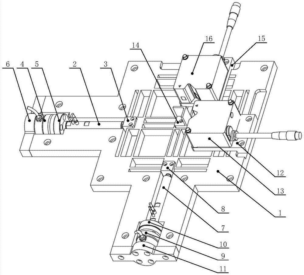
[0032] The present invention will be described in detail below in conjunction with the accompanying drawings.

[0033] First, the component names in the reference numerals will be explained.

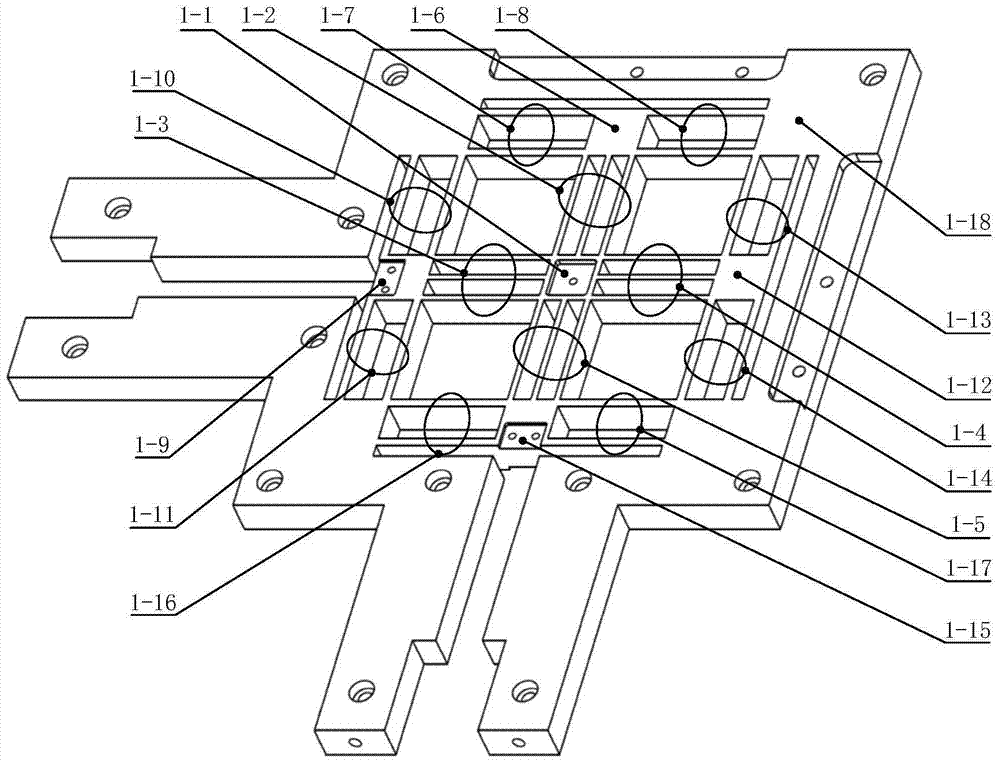
[0034] 1 flexible hinge base;

[0035] 2 a first piezoelectric ceramic actuator;

[0036] 3 first actuator connector;

[0037] 4. The first tension pressure sensor;

[0038] 5 the first flange;

[0039] 6 the first compression cover;

[0040] 7 the second piezoelectric ceramic actuator;

[0041] 8 second actuator connector;

[0042] 9 second tension pressure sensor;

[0043] 10 second flange;

[0044] 11 second compression cover;

[0045] 12 the first mount;

[0046] 13 the first laser displacement sensor;

[0047] 14 measuring base;

[0048] 15 second mount;

[0049] 16 second laser displacement sensor;

[0050] 1-1 terminal rigid output platform;

[0051] 1-2 flexible hinge branches;

[0052] 1-3 flexible hinge branches;

[0053] 1-4 flexible hinge branches;

[0054] 1-...


PUM


Abstract

A two-degree-of-freedom motion decoupling flexible hinge mechanism, the mechanism includes a flexible hinge base and a drive branch, wherein the flexible hinge base includes a flexible hinge branch and a rigid connector, and the rigid connector includes a terminal located in the middle part of the flexible hinge base The rigid output platform and the upper, lower, left, and right rigid platforms respectively located on the upper, lower, left, and right parts of the flexible hinge base; the upper, lower, left, and right rigid platforms respectively pass through the flexible hinge branch chain and the terminal rigid output platform connected, and the upper, lower, left, and right rigid platforms are respectively connected to the rigid base of the flexible hinge base through flexible hinge branches. The two-degree-of-freedom motion decoupling flexible hinge mechanism of the present invention can realize the decoupling between the terminal's all-directional motion and force, thereby helping to improve the motion accuracy of the two-degree-of-freedom motion decoupling flexible hinge mechanism.

Description

technical field [0001] The invention relates to the technical field of mechanical design and manufacture, in particular to the design technology of a high-precision transmission mechanism. Background technique [0002] The micro-motion mechanism has the characteristics of motion precision, high resolution, compact structure, and small motion range. It is widely used in the field of micro-nano manipulation, such as atomic force microscope, photolithography mask platform, fine steel stone turning, precision motion platform, etc. A frequently used micro-motion mechanism is a flexible hinge. The flexible hinge utilizes the micro-deformation and self-recovery properties of elastic materials, eliminates the lost motion and mechanical friction in the transmission process, and can obtain high displacement resolution. Considering that the flexible hinge has no friction, no wear, no lubrication, and has the advantages of compact structure, light weight, easy manufacturing and assembly...

Claims


Application Information

Patent Timeline
Patent Type & Authority Patents(China)
IPC IPC(8): F16C11/12H02N2/02
Inventor 李铁民姜峣杜云松张京雷
Owner TSINGHUA UNIV
Why Eureka
Try Eureka