Bladeless turbine engine

A turbine engine, fanless technology, used in engine components, machines/engines, non-variable-capacity engines, etc., can solve the problem that the centrifugal force of the disc is easy to be stretched, cannot be practically applied, and the disc cannot be overheated. and other problems, to achieve the effect of improving thermodynamic efficiency, preventing overheating deformation, and reducing energy loss

Inactive Publication Date: 2015-09-09
JIMEI UNIV
View PDF5 Cites 4 Cited by
  • Summary
  • Abstract
  • Description
  • Claims
  • Application Information

AI Technical Summary

Problems solved by technology

However, a series of experiments later proved that there are two serious problems in this fanless turbine engine: one is that the disk is easily stretched and twisted by the strong centrifugal force under the ultra-high-speed operation of the rotor, and the disk’s The larger the diameter, the higher the degree of distortion; the second is that the frictional heat generation that cannot be completely avoided during the fluid flow is very easy to cause the disc to overheat but cannot be cooled and protected, and the disc will quickly undergo thermal deformation and cause damage. And the higher the temperature of the fluid, the more serious the phenomenon of thermal deformation; therefore, the idea of ​​this bladeless turbine engine has not been practically applied for more than a century

Method used


Image

  • Bladeless turbine engine
  • Bladeless turbine engine
  • Bladeless turbine engine

Examples


Embodiment Construction

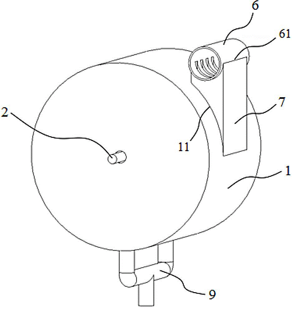
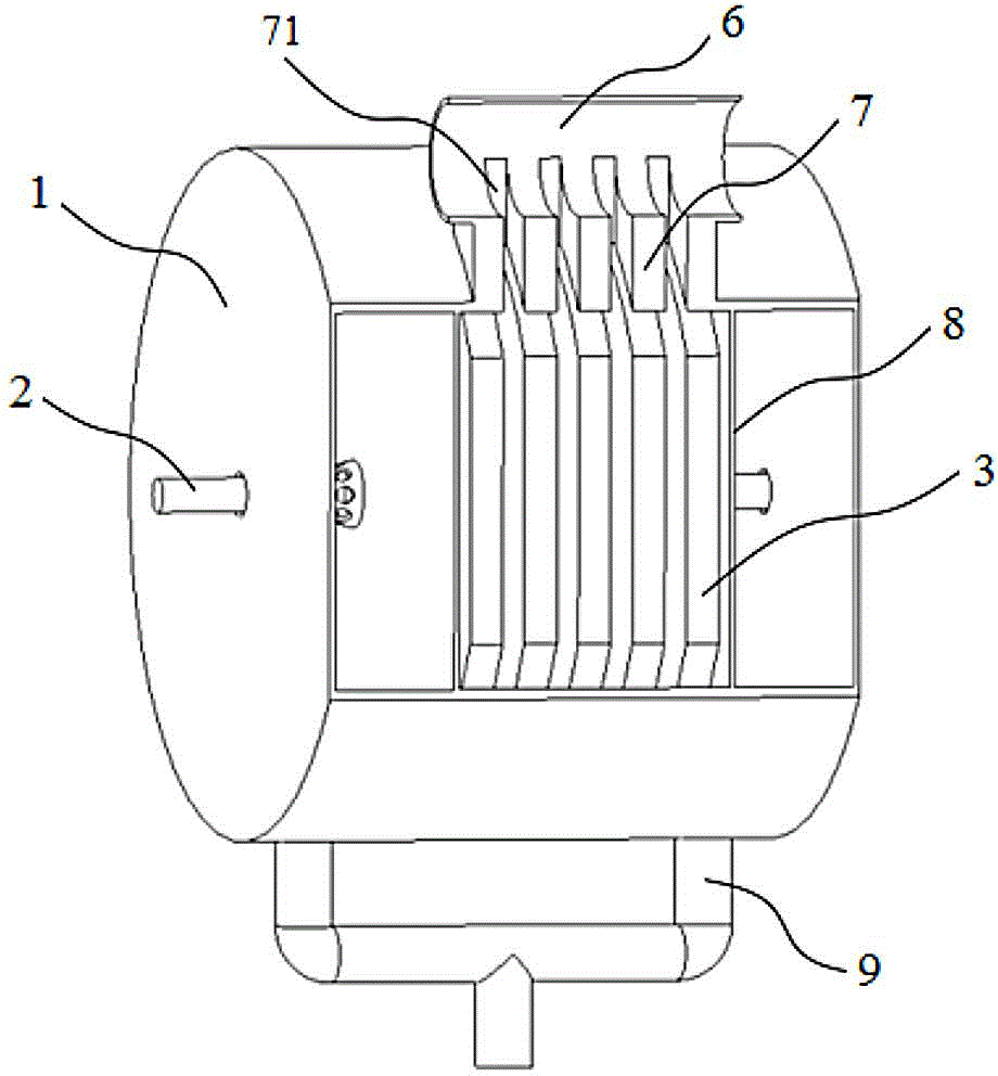
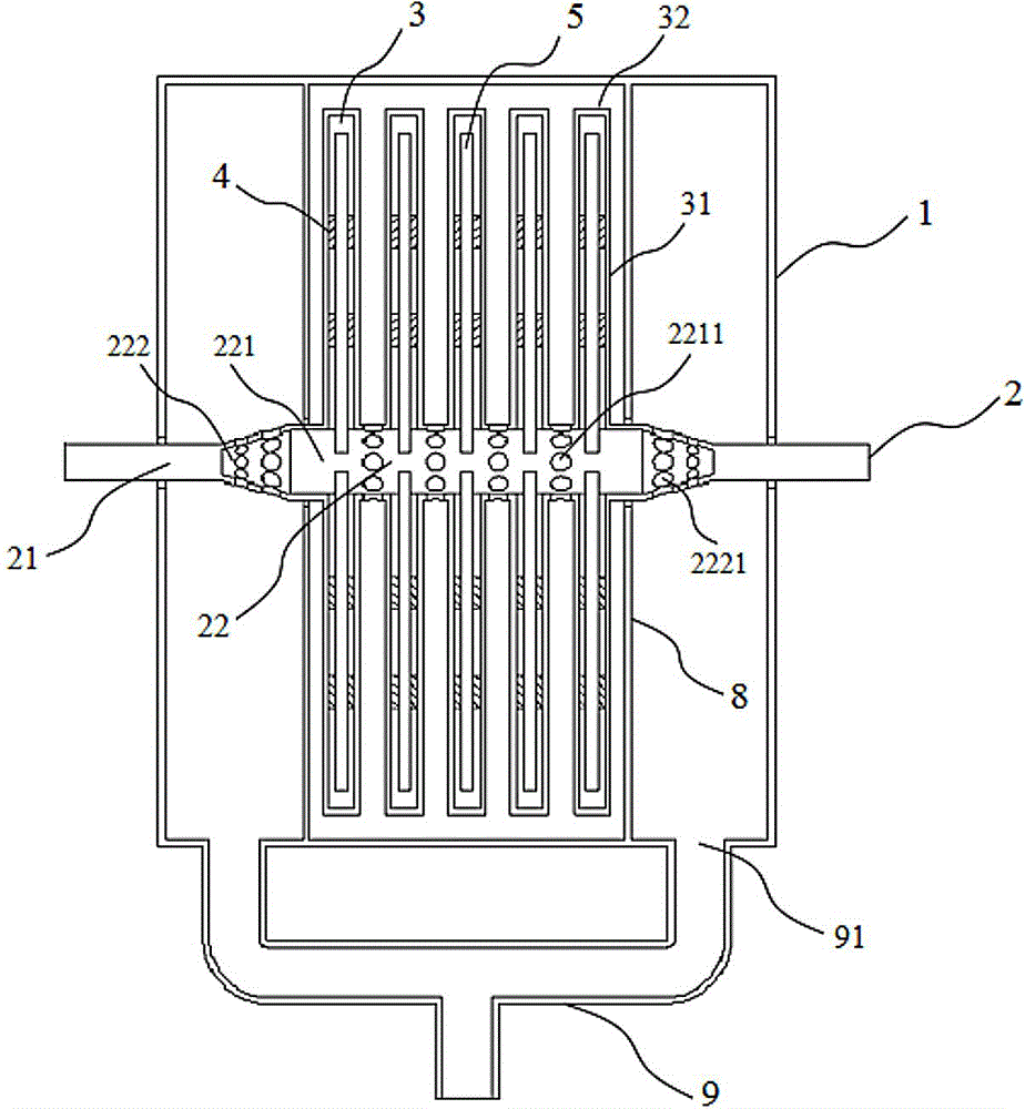
[0022] Such as figure 1 , figure 2 , image 3 , Figure 4 As shown, the present invention is a bladeless turbine engine, which includes a cylinder 1, a rotating shaft 2, a plurality of cavity disc bodies 3, a plurality of pulleys 4, a plurality of heat pipes 5, a steam inlet pipe 6, and a nozzle group 7 , clapboard 8, exhaust pipe 9.

[0023] The cylinder 1 is a hollow cylinder placed horizontally, and a variable-section rotating shaft 2 that runs through the two bottom surfaces of the cylinder is installed on the center line of the cylinder 1. One side of the upper half of the cylinder 1 is provided with several shafts perpendicular to the rotating shaft 2. Rectangular steam inlet group 11; the two ends of the rotating shaft 2 are small-diameter solid shafts 21, the solid shaft 21 extends from the inner cavity of the cylinder 1 to the outside of the cylinder 1, and a steam seal is set at the place where the solid shaft 21 leads out of the cylinder 1 (not shown in the fig...


PUM


Abstract

The invention discloses a bladeless turbine engine. The bladeless turbine engine comprises a cylinder, a rotating shaft, a plurality of empty chamber disk bodies, a plurality of tie bars, a plurality of heat pipes, a steam inlet pipe, a spray pipe group, a separation plate and a steam exhaust pipe. A certain pressure and temperature of viscous fluid spirally and centripetally flows in the cylinder from outside to inside along the circumferential direction after being expanded and accelerated through a spray nozzle and the plurality of empty chamber disk bodies and the rotating shaft are driven to rotate and do work together under the action of shear force of the fluid in a boundary layer. The plurality of different diameters of circular ring tie bars are arranged in every empty chamber disk body for reinforcement, a filled gas cooling medium is used for absorbing the heat dissipation capacity of every empty chamber disk body, and the heat is transferred into an inner chamber of a hollow drum of the rotating shaft from an inner chamber of every empty chamber disk body through the heat pipes to be absorbed through the low temperature exhaust steam eventually. According to the bladeless turbine engine, the energy conversion efficiency is high, the structure is firm and durable, the tensile strength and distortion strength are high, the deformation caused by overhearing is effectively prevented, the unit power is large, and the future application process of the bladeless turbine engine is greatly promoted.

Description

technical field [0001] The invention belongs to the technical field of fluid and power machinery, in particular to a bladeless turbine engine. Background technique [0002] Turbine engine is an engine that uses rotating parts to absorb kinetic energy from fluid passing through it. It is widely used in various fields such as people's life, industrial production, national defense, and aerospace. At present, the commonly used turbine engines are blade turbine engines, including water turbines, wind turbines, steam turbines, gas turbines, etc. Turbine engines with fan blades use fluid to impact the blades to rotate to generate power. The energy conversion efficiency of turbine engines based on this working principle is not high, and the blades are directly impacted by the fluid, which is very easy to break or damage, especially the long and narrow ones. blade. Based on the above-mentioned problems of the turbine engine with fan blades, the great inventor Nikola Tesla once prop...

Claims


Application Information

Patent Timeline
Patent Type & Authority Applications(China)
IPC IPC(8): F01D1/34F01D25/00
Inventor 陈志强蒋俊尧
Owner JIMEI UNIV
Why Eureka
Try Eureka