
Cleaning method of valve body cleaner and device thereof

A cleaning machine and valve body technology, applied in the direction of using liquid cleaning methods, cleaning methods and utensils, chemical instruments and methods, etc., can solve the problems of railway freight car operation safety hazards, blockage of brake air channels, and unsatisfactory cleaning effects, etc. , to achieve the effect of good cleaning effect, simple installation and simple structure

Active Publication Date: 2015-09-09
CRRC GUIYANG CO LTD
View PDF7 Cites 2 Cited by
  • Summary
  • Abstract
  • Description
  • Claims
  • Application Information

AI Technical Summary

Problems solved by technology

Due to the complicated structure of the inner cavity of the valve and many accessories with movement requirements, there are many air channels and the aperture is small, the smallest diameter is only ∮0.2mm, so the dirt and sludge formed during the production and use of the valve If the sundries are not completely removed, it is easy to block the brake air passage, cause brake failure, and bring serious hidden dangers to the operation safety of railway wagons. The existing cleaning method is to place the air brake control valve in a special cleaning equipment , although this kind of equipment has a certain cleaning effect, but in the process of cleaning, the channel of the inner cavity of the valve is completely open, and the cleaning liquid or gas cannot form a high pressure in the inner cavity, and it is often difficult to clean the inner cavity of the valve. It is difficult to clean the dirt in the channel of the inner cavity of the valve, especially the dirt in the groove of the inner cavity of the valve. Therefore, it is necessary to manually carry out the final supplementary cleaning. Therefore, the existing cleaning method of the inner cavity of the railway vehicle valve not only has the cleaning effect It is not ideal enough, and there are still problems of low cleaning efficiency, time-consuming and labor-intensive cleaning

Method used


Image

  • Cleaning method of valve body cleaner and device thereof
  • Cleaning method of valve body cleaner and device thereof

Examples


Embodiment Construction

[0015] The present invention will be further described in detail below in conjunction with the accompanying drawings and embodiments.

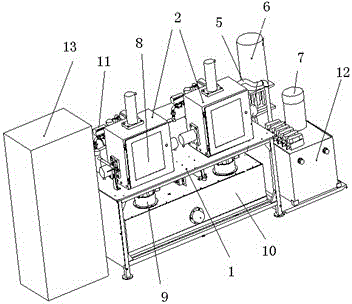
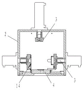
[0016] Embodiments of the present invention: a cleaning method for a valve body cleaning machine. A valve body cleaning chamber is made on the valve body cleaning machine, and a movable clamping module is arranged in the valve body cleaning chamber. The movable clamping module is connected with a hydraulic device, and the valve The body cleaning chamber is connected to the high-pressure water pump and the high-pressure air pump respectively through the inlet pipe, and the valve body cleaning chamber is connected to the discharge pipe. A pneumatic ball valve is made on the inlet pipe and the discharge pipe to control the entry and exit of high-pressure water and compressed air. When cleaning, first Put the valve body to be cleaned into the valve body cleaning chamber, use the movable clamping module to fix the valve body in the center of the val...


PUM


Abstract

The invention discloses a cleaning method of a valve body cleaner and a device thereof. High-pressure water is used for compressing compressed air, so that the compressed air is randomly distributed in the high-pressure water to form high-pressure bubbles; the high-pressure bubbles are exploded in a quick pressure relief manner to generate impact force to damage adhesive force of dirt and impurities attached on the inner wall of a valve body; and finally, the purpose of removing the dirt and the impurities is achieved. The method and the device have the advantages of high cleaning efficiency, good cleaning effect, simple structure and convenience for operation, adopt conventional energy sources, are suitable for conventional environments, and have the beneficial effects of simple installation, low operation cost, convenience for maintenance, safety and environmental protection. The method and the device are specifically suitable for cleaning air brake control valves used on traditional railway vehicles.

Description

technical field [0001] The invention relates to a cleaning method and device of a valve body cleaning machine, in particular to a valve body cleaning machine used for cleaning the inner cavity channel of an air brake control valve of a railway vehicle, belonging to the cleaning technology of the inner cavity of a railway vehicle air valve valve field. Background technique [0002] At present, the air brake control valve (120, 120-1 valve) of railway freight car is the control center and core component of the freight car brake. The production and maintenance quality of 120 valve directly affect the safety of railway operation. Due to the complicated structure of the inner cavity of the valve and many accessories with movement requirements, there are many air channels and the aperture is small, the smallest diameter is only ∮0.2mm, so the dirt and sludge formed during the production and use of the valve If the sundries are not completely removed, it is easy to block the brake...

Claims


Application Information

Patent Timeline
Patent Type & Authority Applications(China)
IPC IPC(8): B08B3/02
CPCB08B9/0321
Inventor 张晓南王小成姚红祥苏必文许明初钟柯谢作运光旭东
Owner CRRC GUIYANG CO LTD
Learn More