Pathogenic microbe and insect pest extermination method and pathogenic microbe and insect pest extermination device
A technology for pathogens and pests, which is applied in the field of pathogen and pest repelling and pathogen and pest repelling devices, can solve the problems of residual pesticides, pathogens and pests that cannot be effectively repelled from crops, etc., and achieves excellent bactericidal effect and excellent repelling effect.
- Summary
- Abstract
- Description
- Claims
- Application Information
AI Technical Summary
Problems solved by technology
Method used
Image

Examples
no. 1 approach
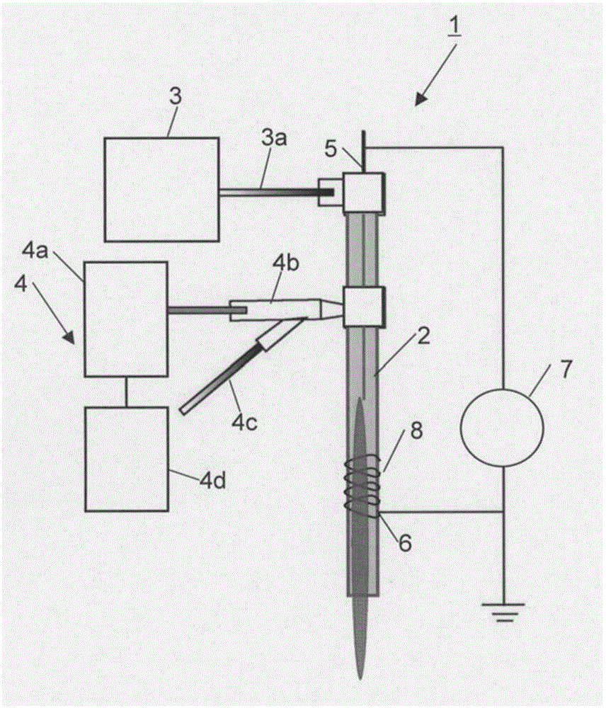
[0067] figure 1 It is a diagram showing a configuration example of the pathogenic bacteria and pest extermination device 1 according to the first embodiment of the present invention. Such as figure 1 As shown, the pathogenic bacteria and pest extermination device 1 according to the first embodiment of the present invention is composed of a reaction container 2, a gas supply part 3, a water supply part 4, a cathode electrode 5 and an anode electrode 6, and a power supply part 7. The gas supply unit 3 supplies gas to the reaction vessel 2; the water supply unit 4 supplies water mist to the reaction vessel 2; the cathode electrode 5 and the anode electrode 6 are arranged outside the reaction vessel.
[0068] The reaction container 2 is a container made of glass such as quartz glass or an insulator such as resin. The anti-gas pipe 3a is connected with the container 2. Furthermore, a cathode electrode 5 and an anode electrode 6 are arranged on the reaction container 2 . The cat...
no. 2 approach
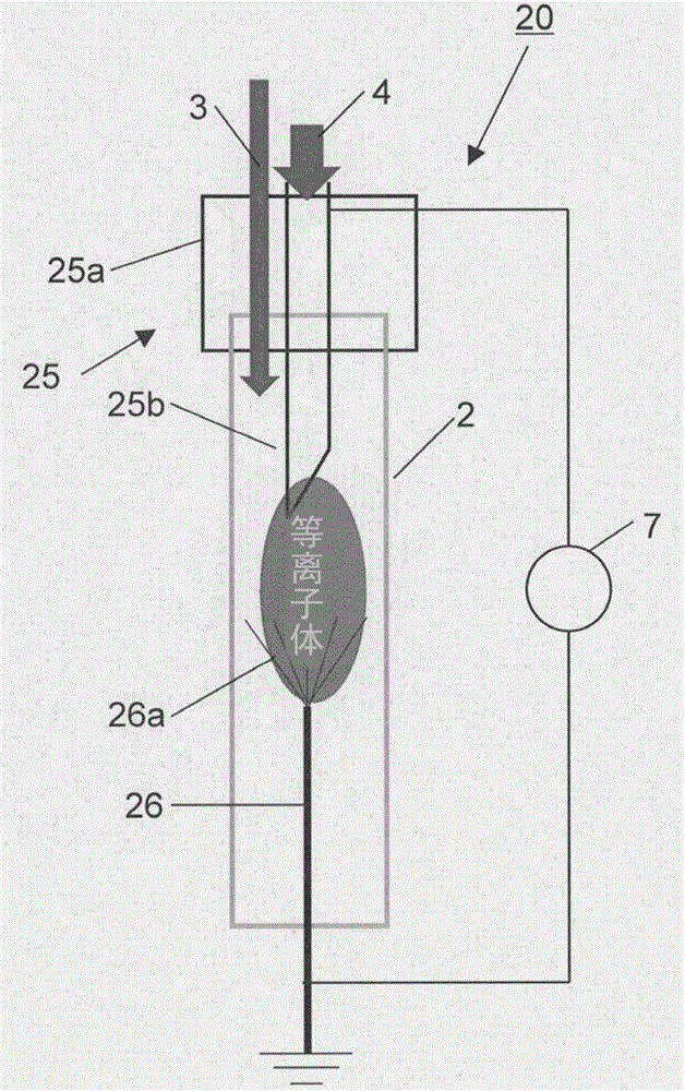
[0079] image 3 It is a figure which shows the structural example of the pathogenic bacteria and pest extermination apparatus 20 which concerns on 2nd Embodiment of this invention.
[0080] image 3 Shown pathogenic bacteria and pest repelling device 20 and figure 1 The difference of the pathogenic bacteria and pest repelling device 1 is that the structures of the cathode electrode 25 and the anode electrode 26, and the water mist are introduced into the reaction vessel 2 from the cathode electrode 25 side.
[0081] The cathode electrode 25 is configured to include a main body portion 25 a connected to the reaction container 2 and an insertion portion 25 b connected to the main body portion 25 a and inserted into the reaction container 2 . The tip of the insertion portion 25b is formed of a thin tube. The water supply part 4 is formed to introduce water mist into the reaction container 2 through the insertion part 25b. The anode electrode 26 is composed of bundled thin wir...
no. 3 approach
[0087] Figure 5 It is a diagram showing a configuration example of a pathogenic bacteria and pest extermination device 30 according to a third embodiment of the present invention.
[0088] Figure 5 Shown pathogenic bacteria and pest repelling device 30, with figure 1 The difference of the pathogenic bacteria and pest repelling device 1 is that the structure of the cathode electrode 25 and water are introduced into the reaction vessel 2 from the cathode electrode 25 side.
[0089] The cathode electrode 25 has a cylindrical insertion portion 25b inserted into the reaction container 2 and a linear body 25c provided at the tip of the insertion portion 25b and composed of thin wires. The front end portion of the insertion portion 25 b of the cathode electrode 25 and the linear body 25 c are arranged inside the outer coil 8 of the anode electrode 26 wound around the reaction vessel 2 . The pathogen and pest repelling device 30 is formed so that water from the water supply part ...
PUM
| Property | Measurement | Unit |
|---|---|---|
| The inside diameter of | aaaaa | aaaaa |
| Outer diameter | aaaaa | aaaaa |
| Length | aaaaa | aaaaa |
Abstract
Description
Claims
Application Information
 - R&D
- Intellectual Property
- Life Sciences
- Materials
- Tech Scout
- Unparalleled Data Quality
- Higher Quality Content
- 60% Fewer Hallucinations
Browse by: Latest US Patents, China's latest patents, Technical Efficacy Thesaurus, Application Domain, Technology Topic, Popular Technical Reports.
© 2025 PatSnap. All rights reserved.Legal|Privacy policy|Modern Slavery Act Transparency Statement|Sitemap|About US| Contact US: help@patsnap.com