Apparatus of increasing coherent beam combination laser beam quality

A technology of laser beam quality and coherent beam combining, applied in optics, optical components, instruments, etc., can solve the problems of non-linear effects of fiber thermal damage, difficulty in designing and manufacturing lens groups, limited focusing power density, etc. The processing technology is mature, the effect of avoiding damage to optical components and avoiding air breakdown

Inactive Publication Date: 2015-08-26
INST OF OPTICS & ELECTRONICS - CHINESE ACAD OF SCI
View PDF2 Cites 6 Cited by
  • Summary
  • Abstract
  • Description
  • Claims
  • Application Information

AI Technical Summary

Problems solved by technology

Among them, the amplitude-phase conversion method uses two special phase plates to suppress the number of side lobes. Since the phase plate is located at the focal plane of the lens, the focusing power density that can be tolerated is very limited, and it is impossible to achieve high-power coherent beam combining; The imaging waveguide method utilizes the self-imaging effect of multimode fiber, which is only suitable for fiber lasers, and is limited by fiber thermal damage and nonlinear effects, and cannot achieve high-power coherent beam combining; the inverse Damman grating method It utilizes the splitting characte

Method used


Image

  • Apparatus of increasing coherent beam combination laser beam quality
  • Apparatus of increasing coherent beam combination laser beam quality
  • Apparatus of increasing coherent beam combination laser beam quality

Examples


Embodiment 1

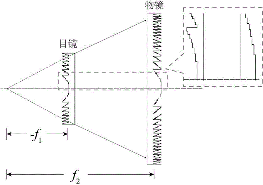
[0038] The apertures of the unit eyepiece and objective are 2R respectively 1 =5mm, 2R 2 =14mm, the focal length is f respectively 1 =-37.5mm, f 2 =105mm. The focal length of the focusing lens is f=1000 mm.

[0039] The phase steps of the fixed eyepiece array and the objective lens array are taken as L=8.

[0040] Figure 5 is the far-field spot distribution of the coherent combined beam. It can be seen that the number of side lobes in the combined beam spot is small, and the surrounding power ratio can be calculated as BQ=1.489.

[0041] As a comparison, Image 6 The far-field spot distribution of the coherent combined beam obtained directly without adding the diffractive telescopic system array is given. Compared Figure 5 It can be seen that the number of side lobes in the combined beam spot is significantly larger, and the surrounding power ratio can be calculated as BQ=3.0225. It can be seen that the use of the 8-step diffractive telescopic system array improves...

Embodiment 2

[0043] The same structural parameters as in Example 1 are adopted, that is, the apertures of the unit eyepiece and the objective lens are respectively 2R 1 =5mm, 2R 2 =14mm, the focal length is f respectively 1 =-37.5mm, f 2 =105mm. The focal length of the focusing lens is f=1000 mm.

[0044] The number of phase steps in different regions is taken as different values, that is, the number of steps in the 5 annular bands in the center of the lens is 32, the number of steps in the 25 outer annular bands is 16, and the number of steps in other annular bands is 8, such as Figure 7 shown.

[0045] Figure 8 Given this surface structure, the far-field coherent combined beam spot distribution is given, and the surrounding power ratio can be calculated as BQ=1.2583. It can be seen that the number of side lobes is further reduced, and the beam quality is improved by 2.4 times compared with the case where the diffractive telescopic system array is not added, and compared with the 8-...


PUM


Abstract

The invention discloses an apparatus of increasing coherent beam combination laser beam quality. The apparatus comprises one set of diffractive telescopic system arrays, one focusing lens and one CCD. The diffractive telescopic system arrays are formed by one set of eye lens arrays and one set of objective lens arrays. Each eye lens and each objective lens form a diffractive telescopic system unit. A unit structure adopts a Galileo telescopic system. A composition lens adopts a multistage phase type Fresnel diffraction structure. The diffractive telescopic system arrays expand incident dispersed array light beams into tangent light beams. Then a focusing lens carries out focusing, far-field coherent beam combination is realized at a focal plane position and the CCD is used to detect energy distribution of beam combination laser. The apparatus possesses the advantages that processing is easy; installation and adjustment are convenient and so on. Simultaneously, the diffractive telescopic system arrays possess high expansibility. Different arrangements and coherent laser beam combination of multi-path high fill factors can be realized.

Description

technical field [0001] The invention relates to the technical field of laser coherent beam combining, in particular to a device for increasing the array beam filling factor by using a diffractive telephoto system array, thereby improving the quality of the coherent combined laser beam. Background technique [0002] High power and high beam quality are the eternal goals of laser technology research. The laser coherent beam combining technology can disperse the Joule heat in the laser working material and avoid the thermal effect and nonlinear effect in the crystal medium when the power is too large. It is an effective way to achieve high power and high beam quality laser output. However, in laser coherent beam combining, due to the existence of coherence, the combined beam spot consists of a central main lobe and a large number of side lobes, the energy is dispersed, and the beam quality is poor. For such complex spots, high beam quality means high energy concentration, and ...

Claims


Application Information

Patent Timeline
IPC IPC(8): G02B27/09G02B27/42
CPCG02B27/0955G02B27/0905G02B27/42
Inventor 周崇喜龚海龙李国俊方亮
Owner INST OF OPTICS & ELECTRONICS - CHINESE ACAD OF SCI
Why Eureka
Try Eureka