Boundary-changing fluid mechanism engine

A fluid mechanism and engine technology, which is applied in the direction of machines/engines, combustion engines, internal combustion piston engines, etc., to achieve the requirements of reducing temperature rise, reducing pressure bearing capacity, and the effect of fewer parts of the whole machine

Active Publication Date: 2016-08-24
浙江巨力宝纺织科技有限公司
View PDF7 Cites 0 Cited by
  • Summary
  • Abstract
  • Description
  • Claims
  • Application Information

AI Technical Summary

Problems solved by technology

[0002] The efficiency problems and pollution emission problems of volumetric power mechanisms represented by gasoline engines and diesel engines have not been well resolved. The fundamental reason is that their timing combustion methods and the volume changes in the compression process and expansion process are the same. These two major problems are caused by the basic structure of this type of engine, which cannot be changed, so a new type of engine needs to be invented

Method used


Image

  • Boundary-changing fluid mechanism engine
  • Boundary-changing fluid mechanism engine
  • Boundary-changing fluid mechanism engine

Examples


Embodiment 1

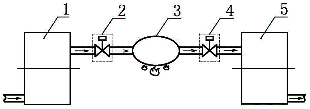
[0042] A variable boundary fluid mechanism engine, such as figure 1 As shown, it includes a variable boundary fluid mechanism 1 for compression, a gas compression control valve 2, a continuous working medium heater 3, a gas expansion control valve 4, and a variable boundary fluid mechanism 5 for expansion. The compression variable fluid mechanism 1, the The gas compression control valve 2, the working medium continuous heater 3, the gas expansion control valve 4 and the expansion fluid mechanism 5 are sequentially connected, and the working fluid inlet of the expansion fluid mechanism 5 is The ratio of the volume flow rate to the volume flow rate at the outlet of the working fluid mechanism 1 for compression is greater than 1.

Embodiment 2

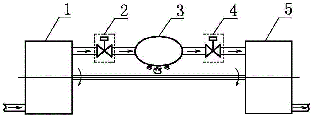
[0044] A variable boundary fluid mechanism engine, such as figure 2 As shown, on the basis of Embodiment 1, the boundary changing fluid mechanism 5 for expansion and the boundary changing fluid mechanism 1 for compression are further arranged in linkage.

Embodiment 3

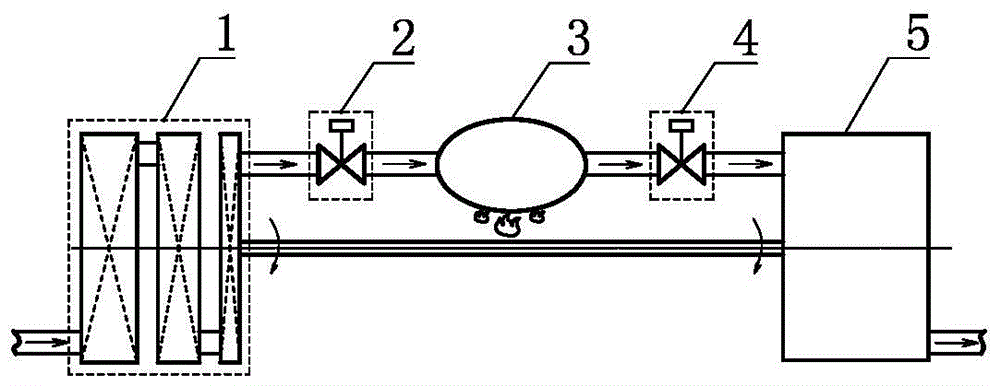
[0046] A variable boundary fluid mechanism engine, on the basis of Embodiment 2, further sets the variable boundary fluid mechanism 5 for expansion and the variable boundary fluid mechanism 1 for compression through a speed change mechanism.


PUM


Abstract

The invention provides an engine of a liquid device with variable boundaries. The engine comprises a liquid device with variable boundaries for compression, a gas compression control valve, a working medium continuous heater, a gas expansion control valve and a liquid device with variable boundaries for expansion, wherein the liquid device with variable boundaries for compression, the gas compression control valve, the working medium continuous heater, the gas expansion control valve and the liquid device with variable boundaries for expansion are communicated in sequence; the ratio of the volume flow rate of the working medium inlet of the liquid device with variable boundaries for expansion to the volume flow rate of the working medium outlet of the liquid device with variable boundaries for compression is bigger than 1. The engine of the liquid device with variable boundaries has few components, is low in cost, stable in operation, low in pollutant discharge and high in watt density and efficiency, and can adopt various bunkers.

Description

technical field [0001] The invention relates to the field of thermal energy and power, in particular to a variable boundary fluid mechanism engine. Background technique [0002] The efficiency problems and pollution emission problems of volumetric power mechanisms represented by gasoline engines and diesel engines have not been well resolved. The fundamental reason is that their timing combustion methods and the volume changes in the compression process and expansion process are the same. These two major problems are caused by the basic structure of this type of engine, which cannot be changed, so a new type of engine needs to be invented. Contents of the invention [0003] In order to solve the above problems, the technical scheme proposed by the present invention is as follows: [0004] Scheme 1: A variable boundary fluid mechanism engine, including a variable boundary fluid mechanism for compression, a gas compression control valve, a continuous working medium heater, ...

Claims


Application Information

Patent Timeline
Patent Type & Authority Patents(China)
IPC IPC(8): F01D15/08F02C3/04F01C13/04F02B53/00
CPCY02T10/12
Inventor 靳北彪
Owner 浙江巨力宝纺织科技有限公司
Why Eureka
Try Eureka