
The method of judging the geological layer where the drill bit is located when the drilling rig drills to a certain depth

A geological layer and depth technology, applied in earthwork drilling, wellbore/well components, measurement, etc., can solve the problems that the physical properties and mechanical parameters of rock formations cannot be obtained, the progress is restricted, and it is difficult to obtain cores, etc., so as to simplify the physical The process of properties and mechanical parameters, the effect of saving engineering time and improving operability

Active Publication Date: 2017-12-08
SHANDONG UNIV
View PDF6 Cites 0 Cited by
  • Summary
  • Abstract
  • Description
  • Claims
  • Application Information

AI Technical Summary

Problems solved by technology

[0004] 1. The long interval from on-site coring to the experimental report in the laboratory seriously restricts the progress of the actual on-site construction and increases the cost of the project budget. At the same time, due to the large number of cores, group numbering, analysis and processing become very heavy , lack of practicality
[0005] 2. It is difficult to guarantee the core recovery rate and integrity when drilling in weak and broken complex formations
When working in unfavorable geological bodies, it is difficult to obtain a complete core that can be used for testing, so that the physical properties and mechanical parameters of the local rock formation cannot be obtained
[0006] 3. Since the core has been evacuated from the original environmental stress, temperature and other constraints, it cannot well represent the strength of the rock mass itself

Method used


Image

  • The method of judging the geological layer where the drill bit is located when the drilling rig drills to a certain depth
  • The method of judging the geological layer where the drill bit is located when the drilling rig drills to a certain depth
  • The method of judging the geological layer where the drill bit is located when the drilling rig drills to a certain depth

Examples


Embodiment Construction

[0032] The above-mentioned objects and advantages of the present invention can be more clearly understood by referring to the detailed description of the preferred embodiments of the present invention with reference to the accompanying drawings.

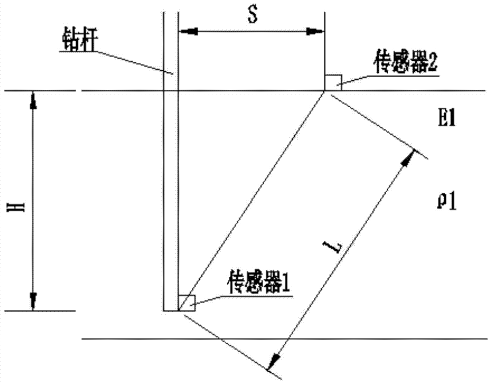
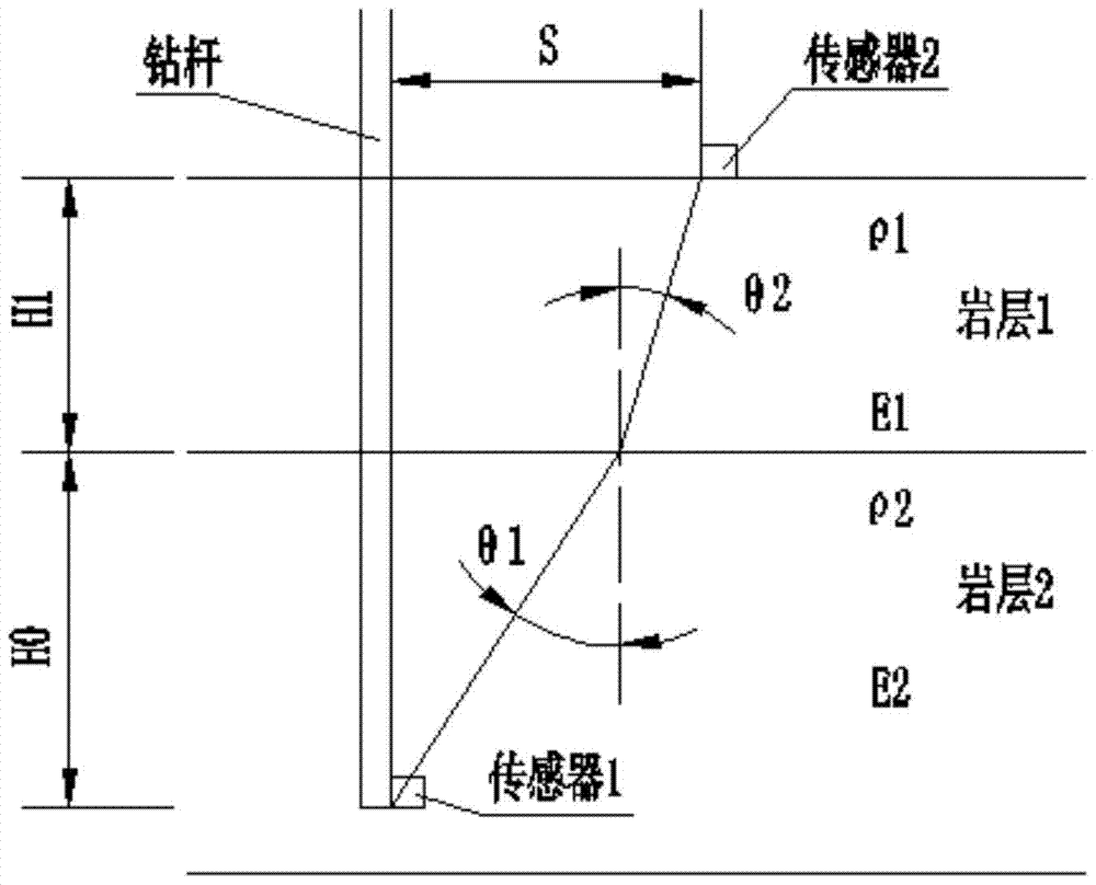
[0033] Such as figure 1 As shown, when the drill pipe is running in the rock formation, measure the P wave generation time t of the sensor 1 installed on the drill bit 1 and the P-wave arrival time t of surface sensor 2 2 , according to the geometric relationship, the propagation distance of P wave can be obtained Then by V=L / (t 2 -t 1 ) can obtain the propagation velocity v of P wave in rock formation 1. The rock core is sampled and collected to determine its density, and the relationship between elastic modulus, P wave propagation velocity and rock density

[0034]

[0035] The modulus of elasticity of the rock formation

[0036]

[0037] and identify the rock formation, where E 1 is the Young's modulus of elasticity ...


PUM


Abstract

The invention discloses a method for judging the geological layer where the drill of a drilling machine drilling for a certain depth is positioned. The method comprises the following steps: 1), obtaining the rock formation density of a target rock formation, P wave velocity and Poisson's ratio Mu, so as to obtain the elastic modulus of the target rock formation through calculation; 2), comparing the elastic modulus of the target rock formation with data in a computer database, so as to obtain the type of the rock formation through analytical judgment; 3), recording the depth when the elastic modulus of the rock formation and the original value of the elastic modulus of the rock formation change suddenly, wherein the depth is the interface depth of the rock formation; 4), repeating the steps (1, 2 and 3), so as to obtain the geological layers where the drill of the drilling machine drilling for different depths are positioned. The method has the advantages that physical properties and mechanical parameters can be obtained through laboratory tests without depending on rock core, real-time analysis and calculation can be carried out according to corresponding data collection when the drilling machine is used for drilling, and the rock formation where the drill is can be judged, so that the process of obtaining the physical properties and mechanic parameters of rock formations of different depths can be simplified greatly, and engineering time is shortened.

Description

technical field [0001] The invention relates to a method for judging the rock strata in real time during the drilling process of a drilling rig, which is suitable for real-time judging of the rock strata where the drill bit is in when the drilling rig is drilling in underground engineering. Background technique [0002] In the past, in order to obtain the physical property parameters of the local rock formation, during the drilling process of the drilling rig, the core tool was often used to drill out the core, and the rock uniaxial compression test was performed in the laboratory, and the core compressive strength test was provided. Report. [0003] However, the method of experimental testing by core sampling has the following problems in practice: [0004] 1. The long interval from on-site coring to the experimental report in the laboratory seriously restricts the progress of the actual on-site construction and increases the cost of the project budget. At the same time, d...

Claims


Application Information

Patent Timeline
Patent Type & Authority Patents(China)
IPC IPC(8): E21B49/00E21B47/00
CPCE21B47/00E21B49/00
Inventor 冯若愚王琦陈瑛李术才高松高红科曾昭楠
Owner SHANDONG UNIV
Learn More