
Automatic robot device for grinding air feeding and discharging edges of blade

A technology of intake and exhaust edges and robots, which is applied in the direction of automatic grinding control devices, grinding machine parts, grinding/polishing equipment, etc., can solve the problems of high-precision grinding and measurement of blades that cannot enter and exhaust edges, Achieve the effects of improving surface machining accuracy and surface quality, ensuring grinding accuracy, and compensating grinding errors

Active Publication Date: 2015-08-26
HUST WUXI RES INST
View PDF7 Cites 51 Cited by
  • Summary
  • Abstract
  • Description
  • Claims
  • Application Information

AI Technical Summary

Problems solved by technology

[0005] In view of the above defects or improvement needs of the prior art, the present invention provides an automatic equipment for grinding the blade intake and exhaust edge grinding robot that integrates self-adaptive grinding and three-dimensional measurement; the present invention uses a six-degree-of-freedom articulated industrial robot as the execution unit , using the tooling method of the positioner to clamp the blade, and using a three-axis motion platform with a three-dimensional laser measuring device for three-coordinate non-contact measurement means, which can solve the problem of high-precision grinding of the blade inlet and exhaust edges in the prior art and measurement issues

Method used


Image

  • Automatic robot device for grinding air feeding and discharging edges of blade
  • Automatic robot device for grinding air feeding and discharging edges of blade
  • Automatic robot device for grinding air feeding and discharging edges of blade

Examples


Embodiment Construction

[0024] In order to make the object, technical solution and advantages of the present invention clearer, the present invention will be further described in detail below in conjunction with the accompanying drawings and embodiments. It should be understood that the specific embodiments described here are only used to explain the present invention, not to limit the present invention. In addition, the technical features involved in the various embodiments of the present invention described below can be combined with each other as long as they do not constitute a conflict with each other.

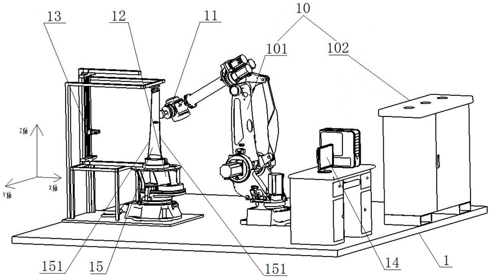
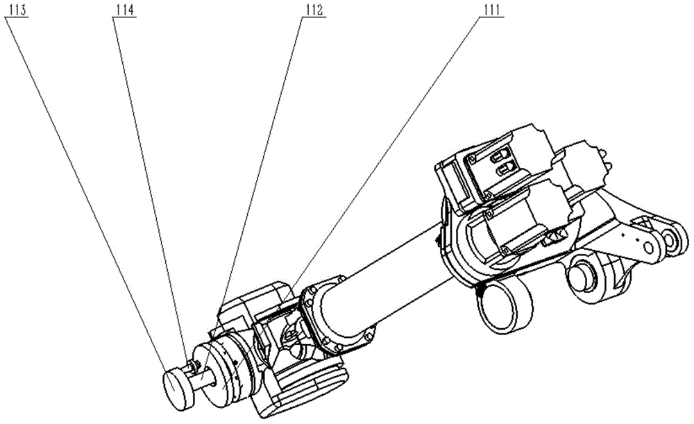
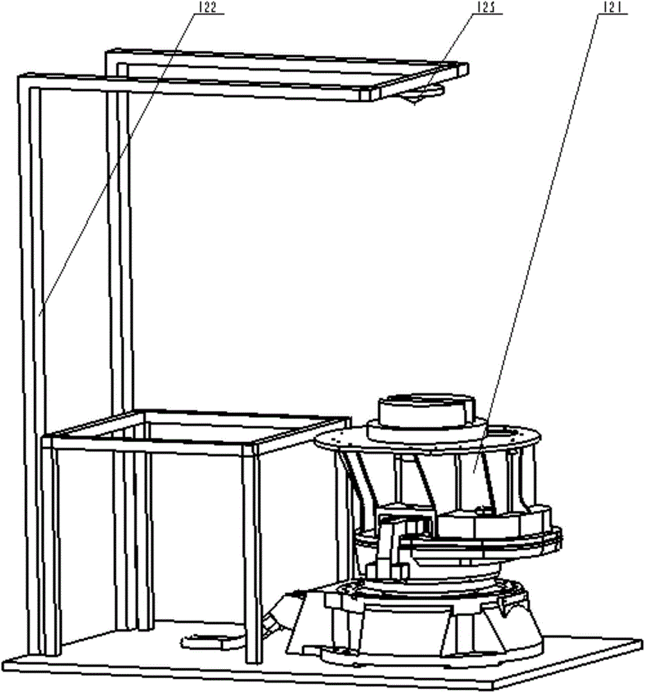
[0025] Such as Figure 1 to Figure 4 As shown, a robot automation equipment for grinding the intake and exhaust edges of blades is used to realize adaptive grinding and three-dimensional measurement of the intake and exhaust edges 151 of blades 15 . The automation equipment includes a six-degree-of-freedom robot 10 , a grinding device 11 , a positioner 12 , a three-dimensional laser measuring d...


PUM


Abstract

The invention discloses an automatic robot device for grinding air feeding and discharging edges of a blade. The automatic robot device comprises a base station, a six-freedom-degree robot, a grinding device, a position changing machine, a three-dimensional laser measurement device and a system control host. The six-freedom-degree robot is arranged on the base station. The grinding device is used for grinding the air feeding and discharging edges of the blade. The position changing machine is arranged on the base station. The three-dimensional laser measurement device is arranged on the position changing machine and comprises a triaxial movement platform and a three-dimensional laser measurement device body. The three-dimensional laser measurement device body comprises two three-dimensional laser outline scanners. The system control host is connected with the six-freedom-degree robot and the three-dimensional laser measurement device. The system control host is used for planning the machining path of the grinding device and a moving path of the three-dimensional laser measurement device and sending the paths and commands to the six-freedom-degree robot to be executed. The automatic robot device integrates self-adaptive grinding and measurement functions, and can guarantee the machining precision of the outlines of the air feeding and discharging edges of the blade.

Description

technical field [0001] The invention belongs to the field of robot processing, and more specifically relates to a robot automation equipment for grinding the inlet and outlet edges of blades. Background technique [0002] Blades are the most numerous key components in aero-engines, gas turbines, and steam turbines and directly participate in energy conversion. The machining accuracy and surface quality of the inlet and exhaust edges directly determine the performance, operating efficiency, and service life of power equipment. Therefore, after precision forging, precision casting, cold rolling or machining, the blades need to be ground on the intake and exhaust edges to ensure contour accuracy and surface finish. At present, mastering the high-efficiency and high-precision grinding technology of blade intake and exhaust edges is of great significance for improving the manufacturing level of blades in my country and promoting the development of aviation, energy and national de...

Claims


Application Information

Patent Timeline
Patent Type & Authority Applications(China)
IPC IPC(8): B24B19/14B24B49/12B24B41/06B24B51/00
CPCB24B19/14B24B41/06B24B49/12B24B51/00B25J11/0065
Inventor 丁汉赵欢林阳赵鑫李祥飞谭超
Owner HUST WUXI RES INST
Learn More