
Melting pool melting furnace

A molten pool smelting furnace and furnace body technology, applied in the field of molten pool smelting furnace, can solve the problems that the materials added at the top are easy to float on the surface of the melt, cannot fully participate in the molten pool, and affect production efficiency, etc., so as to prolong the effective working time , Improve bed energy rate, reduce construction difficulty and construction cost

Active Publication Date: 2018-04-13
CHINA ENFI ENGINEERING CORPORATION
View PDF8 Cites 1 Cited by
  • Summary
  • Abstract
  • Description
  • Claims
  • Application Information

AI Technical Summary

Problems solved by technology

[0002] A relatively common problem in molten pool smelting metallurgical furnaces in the related art is that the materials fed into the furnace from the feeding port tend to float on the surface of the melt, and cannot fully participate in the molten pool reaction, which affects production efficiency and sometimes even fails to produce normally.
For example, in the side-blowing smelting technology in the related art, the side-blowing lance blows toward the center of the furnace body, and the blowing produces a certain stirring effect on the melt in the furnace, but the materials added at the top tend to float on the surface of the melt, making it difficult to enter the melt. Participate fully in the response
Although the top-blowing smelting technology in the related art can stir the molten pool, the working principle of the top-blowing lance makes the melt roll up and down too violently in the furnace. In order to avoid splashing, the top-blowing furnace must increase the height of the furnace body, which leads to the construction of the furnace body. Difficult to increase the cost of furnace body and spray gun

Method used


Image

  • Melting pool melting furnace
  • Melting pool melting furnace

Examples


Embodiment Construction

[0021] Embodiments of the invention are described in detail below, examples of which are illustrated in the accompanying drawings. The embodiments described below by referring to the figures are exemplary and are intended to explain the present invention and should not be construed as limiting the present invention.

[0022] In describing the present invention, it is to be understood that the terms "center", "longitudinal", "transverse", "length", "width", "thickness", "upper", "lower", "front", " Back", "Left", "Right", "Vertical", "Horizontal", "Top", "Bottom", "Inner", "Outer", "Clockwise", "Counterclockwise", "Axial", The orientation or positional relationship indicated by "radial", "circumferential", etc. is based on the orientation or positional relationship shown in the drawings, and is only for the convenience of describing the present invention and simplifying the description, rather than indicating or implying the referred device or element Must be in a particular o...


PUM


Abstract

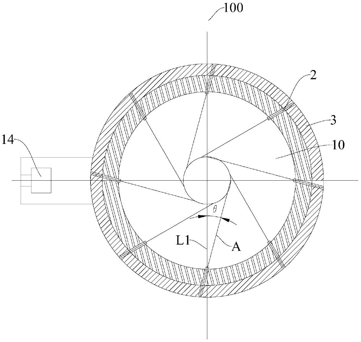
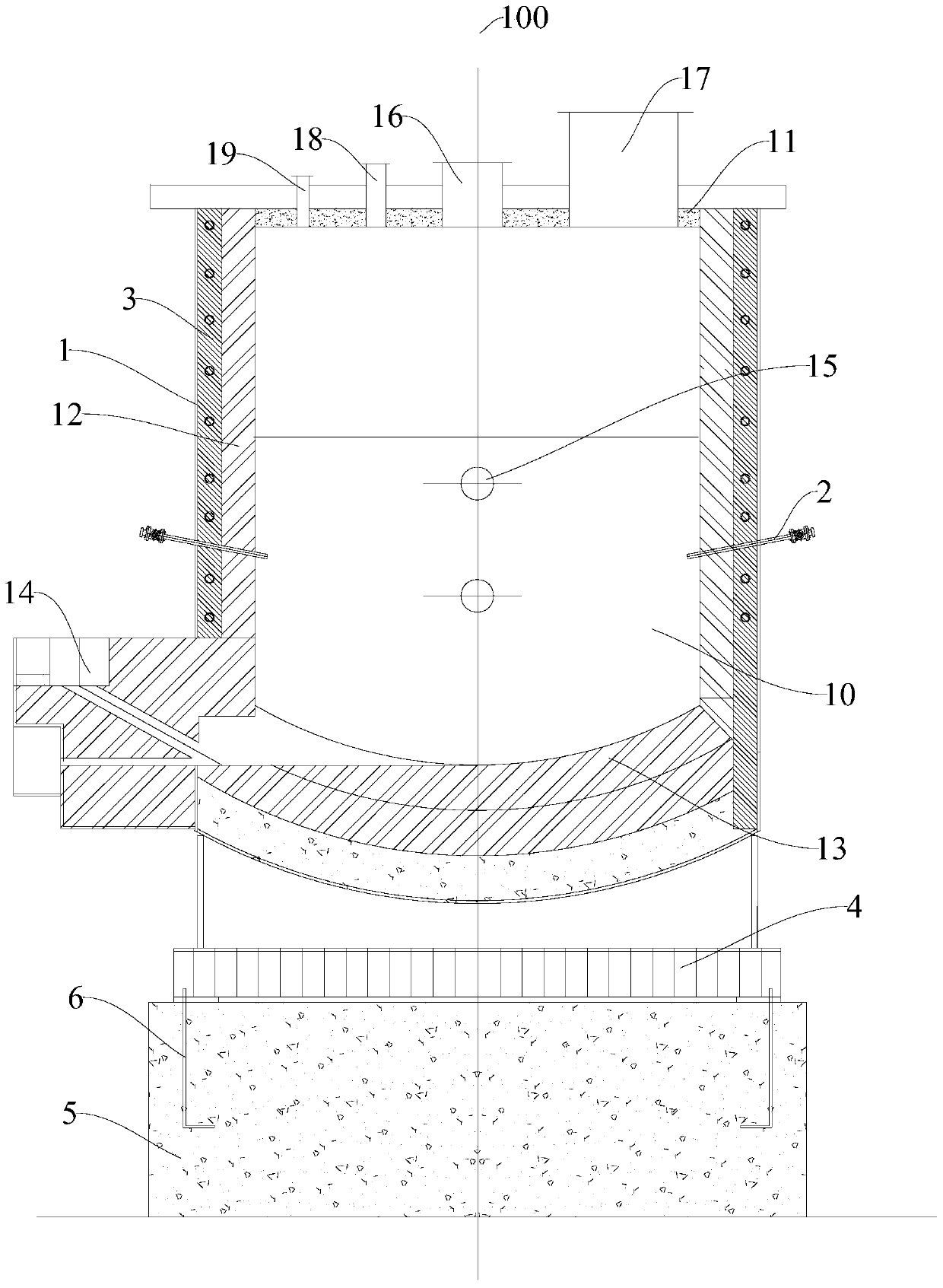
The invention discloses a molten pool smelting furnace, which comprises: a furnace body and a plurality of spray guns. The furnace body has a furnace chamber with a circular cross section. multiple spray gun sockets. The spray guns are inserted into the spray gun sockets, and the multiple spray guns deviate from the center of the circular cross-section of the furnace cavity along the same direction. The melting pool melting furnace according to the embodiment of the present invention has the advantages of low energy consumption and good melting effect.

Description

technical field [0001] The invention relates to a nonferrous metallurgical equipment, in particular to a melting pool melting furnace. Background technique [0002] A relatively common problem in molten pool smelting metallurgical furnaces in the related art is that the materials fed into the furnace from the feed port tend to float on the surface of the melt, and cannot fully participate in the molten pool reaction, affecting production efficiency, and sometimes even cannot produce normally. For example, in the side-blowing smelting technology in the related art, the side-blowing lance blows toward the center of the furnace body, and the blowing produces a certain stirring effect on the melt in the furnace, but the materials added at the top tend to float on the surface of the melt, making it difficult to enter the melt. body fully participates in the reaction. Although the top-blowing smelting technology in the related art can stir the molten pool, the working principle o...

Claims


Application Information

Patent Timeline
Patent Type & Authority Patents(China)
IPC IPC(8): F27B14/00F27B14/14F27D1/00F27D1/12
Inventor 李东波黎敏陈学刚曹珂菲邬传谷姚建明邢国华吴卫国
Owner CHINA ENFI ENGINEERING CORPORATION
Learn More