A new type of pipeline gas automatic water removal device

A gas and pipeline technology, which is applied in the field of new pipeline gas automatic water removal devices, can solve problems such as equipment failures, enterprise economic losses, gas leakage accidents, etc., and achieve the effects of avoiding equipment water inlet failures, reasonable design, and low manufacturing costs.

Inactive Publication Date: 2017-07-21
LUOYANG INST OF SCI & TECH
View PDF10 Cites 0 Cited by
  • Summary
  • Abstract
  • Description
  • Claims
  • Application Information

AI Technical Summary

Problems solved by technology

[0003] In the prior art, the design, manufacture, maintenance, and use of water eliminators in the gas system are relatively simple, and it usually requires manual drainage during use and management
However, in recent years, due to the rapid development of the application of gas in the metallurgical industry, the number of drains in the gas system has increased. Due to fatigue or other reasons, people often forget to drain water regularly, so that the gas will bring moisture into the equipment and cause equipment failure. Bring economic losses, serious will also cause gas leakage accidents, causing harm to the society

Method used


Image

  • A new type of pipeline gas automatic water removal device

Examples


Embodiment Construction

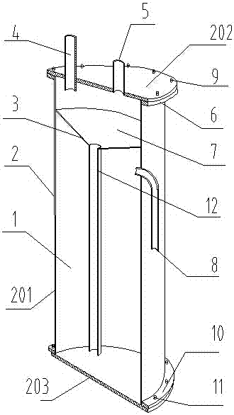
[0017] A new type of pipeline gas automatic water removal device includes a cylindrical water collector 2. The water collector 2 includes a cylindrical body 201, an upper end plate 202 and a lower bottom plate 203 respectively connected to the upper and lower ends of the cylinder 201. The cylinder 201 is provided with a funnel-shaped separator 3, the upper opening periphery of the separator 3 is fully welded and sealed with the inner wall of the cylinder 201, and the separator 3 divides the entire internal space of the cylinder 201 into a vent 7 The venting part 7 and the water storage part 1 are communicated with the water collection pipe 12 at the bottom of the funnel-shaped partition. The upper end plate 202 is provided with a gas inlet and a gas outlet. On the side wall of the cylinder 201, an overflow port is provided in communication with the water storage unit 1. The bottom of the water collection pipe 12 is separated from the water overflow by the accumulation of water ...


PUM


Abstract

A new type of automatic water removal device for pipeline gas, comprising a cylindrical water collector, the water collector includes a cylinder body, an upper end plate and a lower bottom plate respectively connected to the upper and lower ends of the cylinder body, and a funnel is arranged in the cylinder body Shaped spacer, the upper edge of the spacer is sealed and connected with the inner wall of the cylinder, the spacer divides the entire interior space of the cylinder into two parts, the ventilation part and the water storage part, and the ventilation part and the water storage part The upper end plate is provided with a gas inlet and a gas outlet, and on the side wall of the cylinder, an overflow port is provided to communicate with the water storage part. The invention is reasonable in design, convenient and practical, and has low manufacturing cost. It has the function of automatic water release, which can avoid water inflow failure of equipment or safety accidents of gas leakage caused by human negligence.

Description

Technical field [0001] The invention relates to a gas dewatering device, in particular to a novel pipeline gas automatic dewatering device. Background technique [0002] Metallurgical industry by-product gas and producer cold gas are usually used wet dust removal technology to purify and remove dust before they are used. Therefore, the gas contains a lot of water vapor and water mist. Even if the dry dust removal method is used, water vapor and water mist are often formed due to metallurgical raw materials and moisture introduced in the production process. These water vapor and water mist are carried by the gas stream into the gas pipe network system. Therefore, due to the decrease in temperature and environmental changes during the gas transportation process, a large amount of condensed water will be generated. Therefore, the cold gas system must be equipped with a dewaterer to discharge the deposited water. Condensate in the gas system. [0003] In the prior art, the design, ma...

Claims


Application Information

Patent Timeline
Patent Type & Authority Patents(China)
IPC IPC(8): F17D3/14
Inventor 董晓梅
Owner LUOYANG INST OF SCI & TECH
Why Eureka
Try Eureka