
Anti-fatigue reinforcing device for concrete filled steel pipe truss structure nodes and construction method thereof

A steel pipe concrete and truss structure technology, applied in truss bridges, bridge reinforcement, erection/assembly of bridges, etc., can solve the problems of stress concentration at the welding seam, large damage to the original steel pipe structure, unfavorable later maintenance, etc., to achieve The effect of simple structure, reduced fatigue stress range and convenient construction

Active Publication Date: 2015-08-19
ENG DETECTION & REINFORCING CO LTD OF HENAN PROVINCIAL COMM PLANNING SURVEY & DESIGN INST CO LTD
View PDF6 Cites 4 Cited by
  • Summary
  • Abstract
  • Description
  • Claims
  • Application Information

AI Technical Summary

Problems solved by technology

However, reinforcement with built-in stiffening ring and reinforcement with built-in insert plate are only suitable for joint reinforcement in the construction stage, and the operation is complicated and the construction is difficult, which is not conducive to later maintenance; the reinforcement of the ring mouth plate needs to weld multiple welds on the main pipe of the original steel pipe, and the original steel pipe Structural damage is relatively large; external stiffeners are reinforced by adding stiffeners between the main pipe and the branch pipes for reinforcement, but this method cannot solve the problem of stress concentration at the weld

Method used


Image

  • Anti-fatigue reinforcing device for concrete filled steel pipe truss structure nodes and construction method thereof
  • Anti-fatigue reinforcing device for concrete filled steel pipe truss structure nodes and construction method thereof
  • Anti-fatigue reinforcing device for concrete filled steel pipe truss structure nodes and construction method thereof

Examples


Embodiment Construction

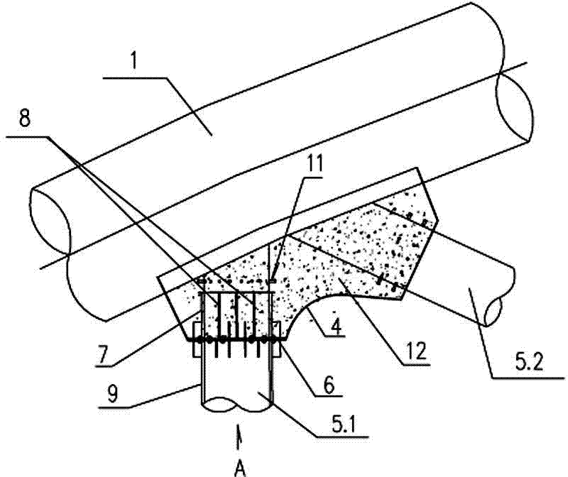
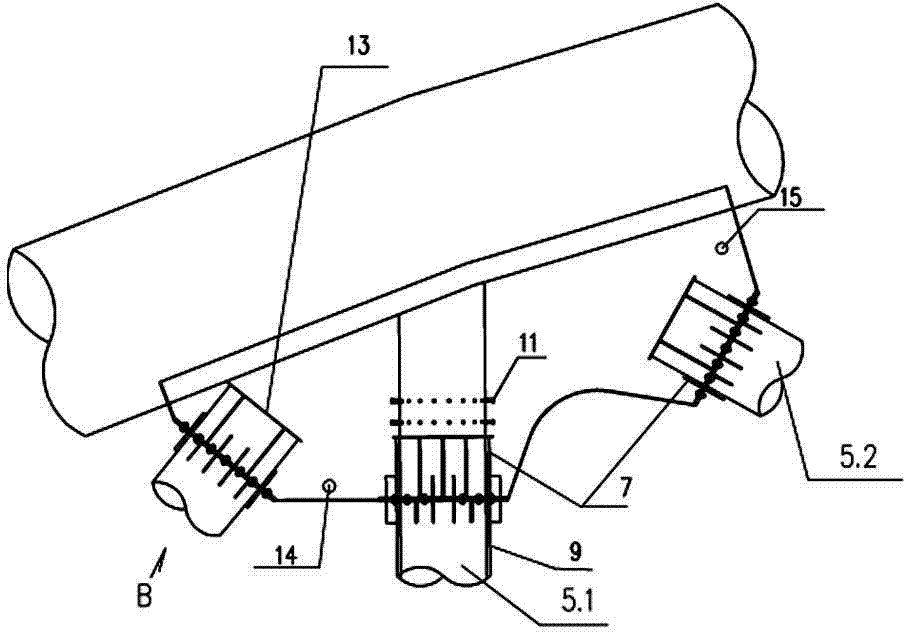
[0027] Such as Figure 1-2 As shown, the anti-fatigue reinforcement device for steel pipe concrete truss structure nodes according to the present invention includes upper and lower guard plates 2,3 welded at the node of the upper chord 1, and the upper and lower guard plates 2,3 are welded on The side sealing plate 4 on the outer edge forms a closed node cavity; the webs (including straight webs 5.1 and oblique webs 5.2) located in the node cavity are sequentially fitted with flanges 6 and reinforcing tubes 7, and the reinforcing tubes 7 The lower end is fixedly connected to the flange 6 attached to the inner surface of the side sealing plate, and a plurality of connecting steel plates 8 are welded between the reinforcing tube 7 and the upper and lower guard plates 2 and 3; located on the web bar 5 outside the node cavity Attached tube 9 is set, and the upper end of the attached tube 9 is fixed on the flange 6 through connecting bolts; the reinforced tube 7 near the flange 6 a...


PUM


Abstract

The invention discloses an anti-fatigue reinforcing device for concrete filled steel pipe truss structure nodes. The device comprises an upper protection plate and a lower protection plate which are welded on at the position of an upper chord node. The upper protection plate and the lower protection plate form a closed node cavity through lateral seal plates welded on the outer edges. A web member located in the node cavity is sequentially by a flange and a reinforcing pipe, the lower end of the reinforcing pipe is fixedly connected onto the flange clinging to the inner surface of the lateral sealing plates, and a plurality of connection steel plates are welded between the reinforcing pipe and the upper protection plate and the lower protection plate. An attached pipe sleeves the web member located on the outside of the node cavity, and the upper end of the pipe is fixedly connected onto the flange through a connection bolt. A specific construction method is further disclosed. The reinforcing device is simple in structure and convenient to construct. The advantage of reserving steel pipe direct welding nodes is achieved, the shortcoming of stress concentration is overcome by adding the node protection plates, and anti-fatigue performance of the nodes is effectively improved. Meanwhile, the straight web member and the inclined web member which can be replaced are provided in the node reinforcing mode, and the structure redundancy is improved.

Description

technical field [0001] The invention relates to road and railway bridge technology, in particular to an anti-fatigue reinforcement device for joints of steel tube concrete truss structures, and also relates to a construction method of the anti-fatigue reinforcement device. Background technique [0002] Concrete filled steel tube is an excellent composite structural material, which greatly improves the compressive performance of the material by utilizing the restraint effect of the external steel tube on the core concrete. In view of the strong compressive properties of CFST, CFST structures are widely used in the highway transportation industry, such as CFST temporary supports, CFST bridge piers, CFST arch bridges, CFST truss bridges, etc. [0003] Concrete-filled steel tube truss bridge is a structural bridge using concrete-filled steel tube materials. It uses concrete-filled steel tube members with strong compressive capacity as the upper chord of the truss, steel pipes w...

Claims


Application Information

Patent Timeline
IPC IPC(8): E01D22/00E04G23/02
CPCE01D6/00E01D22/00
Inventor 李斐然李国普刘雪杨晴郭小帅王康
Owner ENG DETECTION & REINFORCING CO LTD OF HENAN PROVINCIAL COMM PLANNING SURVEY & DESIGN INST CO LTD
Learn More