
Efficient and safe oil press with preheating function

A hydraulic press and preheating technology, applied in the field of hydraulic presses, can solve the problems of easily causing industrial accidents, difficulty in alignment, danger to workers, etc., and achieve the effects of improving safety and reliability, improving work efficiency, and avoiding softening and deformation.

Inactive Publication Date: 2015-08-19
中山市八达机器制造有限公司
View PDF9 Cites 9 Cited by
  • Summary
  • Abstract
  • Description
  • Claims
  • Application Information

AI Technical Summary

Problems solved by technology

Finally, through the check valve, the hydraulic oil is circulated in the oil tank to make the oil cylinder / piston circulate to do work, so as to complete a certain mechanical action as a kind of productivity machine. However, in the actual working process, the seal will be damaged after long-term work. Once the parts are damaged, the upper platen of the hydraulic press will slide down, which is very dangerous for the staff who are changing the mold, cleaning the mold or changing the material, and it is easy to cause industrial accidents
[0003] Moreover, when the hydraulic press stamps certain workpieces such as plastic parts, aluminum parts with special requirements, and sheet metal parts, it is necessary to preheat the above-mentioned workpieces to improve the quality of the stamped products. However, the traditional hydraulic press operation process In the process, the workpiece is usually heated by external heating equipment and then moved to the mold. However, after the workpiece is preheated, especially the plastic workpiece, it is easy to soften and deform. During the process of moving and placing, it is difficult to align or even partially deformed. , bending, reducing the efficiency and quality of stamping processing

Method used


Image

  • Efficient and safe oil press with preheating function
  • Efficient and safe oil press with preheating function
  • Efficient and safe oil press with preheating function

Examples


Embodiment Construction

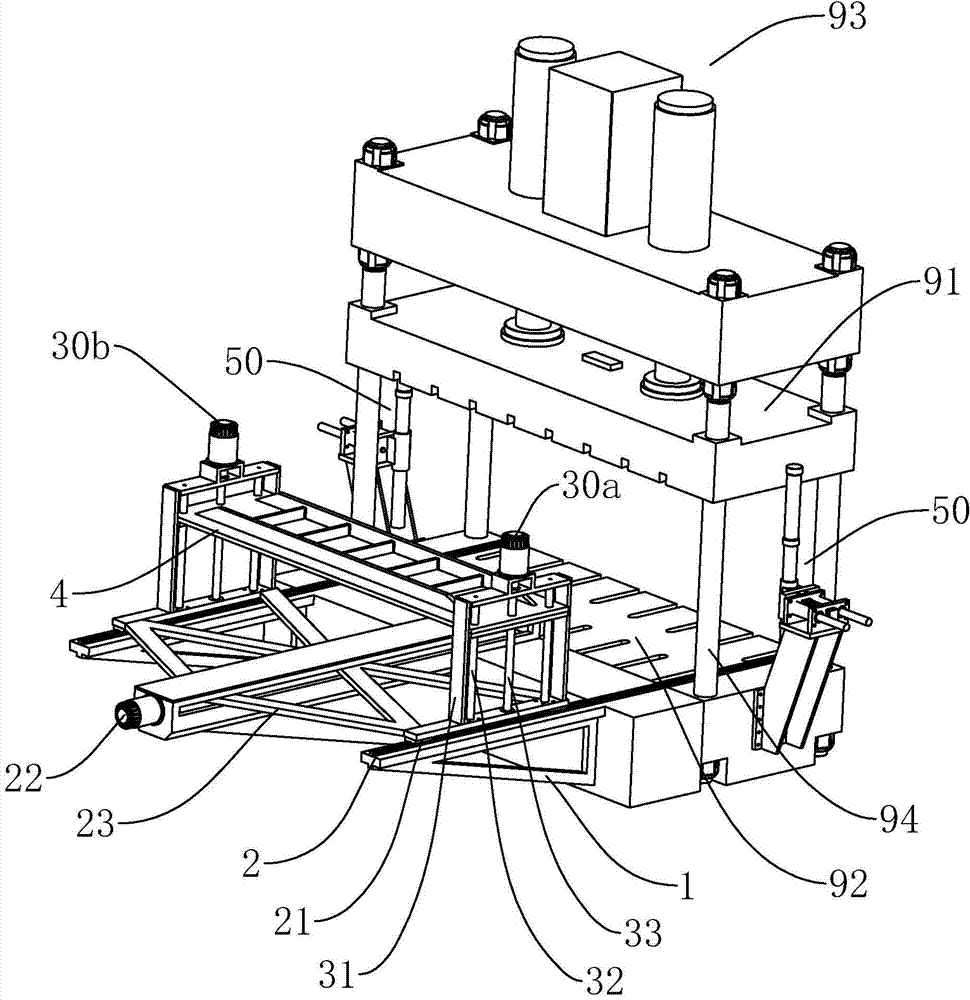
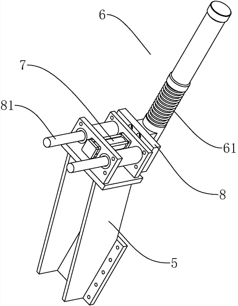
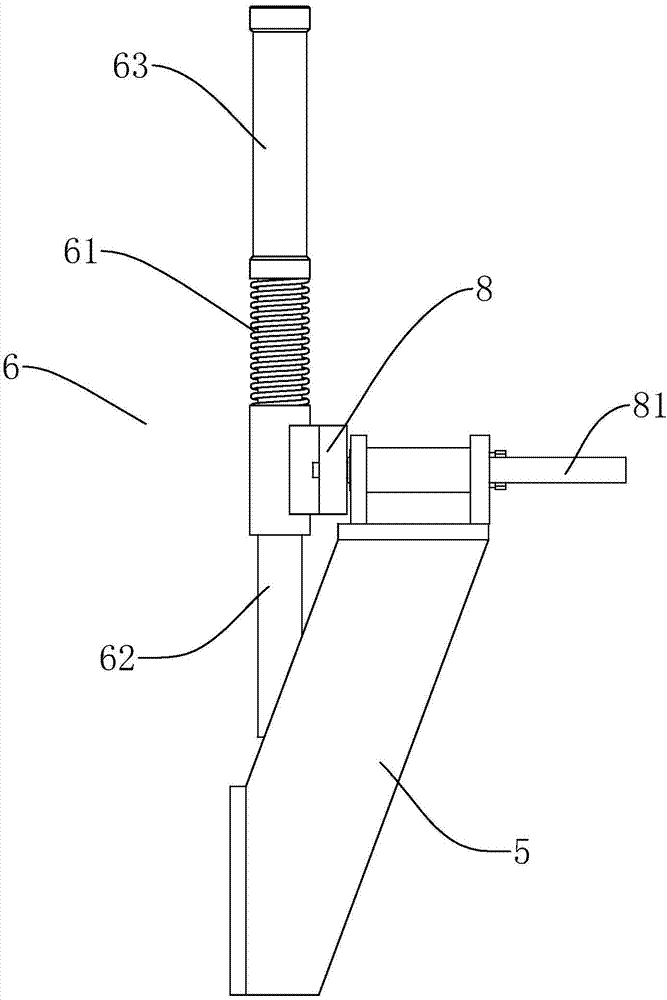
[0022] refer to Figure 1 to Figure 3 , Figure 1 to Figure 3 It is a structural schematic diagram of a specific embodiment of the present invention. As shown in the figure, a high-efficiency and safe hydraulic press with preheating function includes a hydraulic press body, and the hydraulic press body includes a frame, a hydraulic system 93, a column 94, and an upper platen 91 , the lower pressing plate 92, a beam is arranged above the column 94, the hydraulic system 93 is arranged on the beam and connected with the upper pressing plate 91, the upper pressing plate 91 is slidably arranged on the column 94, and the lower pressing plate 92 is located below the column 94, The upper mold and the lower mold of the stamping die are fixed on the upper pressing plate 91 and the lower pressing plate 92 respectively.

[0023] Such as figure 1 As shown, the hydraulic press body also includes a preheating system. The preheating system includes a lateral movement device, an up and down ...


PUM


Abstract

The invention discloses an efficient and safe oil press with a preheating function. The efficient and safe oil press comprises a rack, a hydraulic system, uprights, an upper pressing plate, a lower pressing plate, a safe supporting system and a preheating system. The safe supporting system comprises a support, a moving device and supporting rods, and the preheating system comprises a transverse moving device, an up-down moving device and a heating device. During working, a workpiece is placed on the heating device for preheating, the heating device is moved to space above a lower die through the transverse moving device, and the workpiece is accurately placed on the lower die through the up-down moving device, so that the workpiece is effectively avoided softening and deforming after being heated, punching quality is improved, and working efficiency of the oil press is improved; when punching is completed, the upper pressing plate is moved to set height, the moving device disposes the supporting rod between the upper pressing plate and the lower pressing plate so as to play a role in supporting the upper pressing plate and the lower pressing plate, so that the circumstance that working personnel is pressed and injured due to the fact that the upper pressing plate accidentally falls down is prevented, and safety and reliability of the oil press are improved.

Description

technical field [0001] The invention relates to an efficient and safe hydraulic press with preheating function. Background technique [0002] The hydraulic press is a kind of special hydraulic oil as the working medium and the hydraulic pump as the power source. The force of the pump makes the hydraulic oil enter the cylinder / piston through the hydraulic pipeline, and then there are several sets of seals in the cylinder / piston that cooperate with each other. , The seals in different positions are different, but they all play a role in sealing, so that the hydraulic oil cannot leak. Finally, through the one-way valve, the hydraulic oil circulates in the oil tank to make the cylinder / piston circulate to do work, so as to complete a certain mechanical action as a kind of productivity machine. However, in the actual working process, the seal will be damaged after long-term work. Once the parts are damaged, the upper platen of the hydraulic press will slide down, which is very d...

Claims


Application Information

Patent Timeline
Patent Type & Authority Applications(China)
IPC IPC(8): B21D22/02B21D37/16B21D43/00B21D55/00B30B15/00
CPCB21D22/02B21D37/16B21D43/00B21D55/00
Inventor 颜俊杰李卫兵晏昌荣
Owner 中山市八达机器制造有限公司
Learn More