Coupling type negative ion generating device and equipment applied with the same
A negative ion generation and coupling technology, applied in the direction of electrical components, etc., can solve problems such as simple and effective control methods and devices that have not yet been seen, and achieve the effects of reducing the possibility, eliminating direct electric shock, and improving health
- Summary
- Abstract
- Description
- Claims
- Application Information
AI Technical Summary
Problems solved by technology
Method used
Image
Examples
Embodiment 1
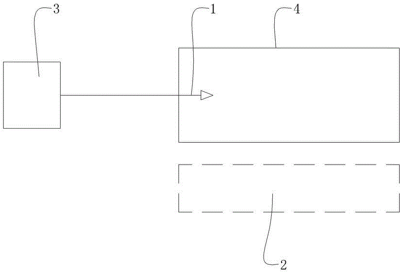
[0032] The coupling type negative ion generator of this embodiment, see figure 1 , Including active discharge body 1, induction discharge body 2 and negative high voltage generator 3. The output terminal of the negative high voltage generator 3 is connected to the input terminal of the active discharge body 1, and the active discharge body 1 and the induction discharge body 2 are in a space range where mutual electric charge can be induced. A solid insulating medium 4 is provided between the active discharge body 1 and the induction discharge body 2 to electrically isolate the active discharge body 1 and the induction discharge body 2 to form only charge induction.
[0033] When the negative high voltage generator 3 supplies power to the active discharge body 1, the active discharge body 1 and the induction discharge body 2 form a capacitor, and the induction discharge body 2 senses the charge released by the active discharge body 1 to generate induced charges and then releases to...
Embodiment 2
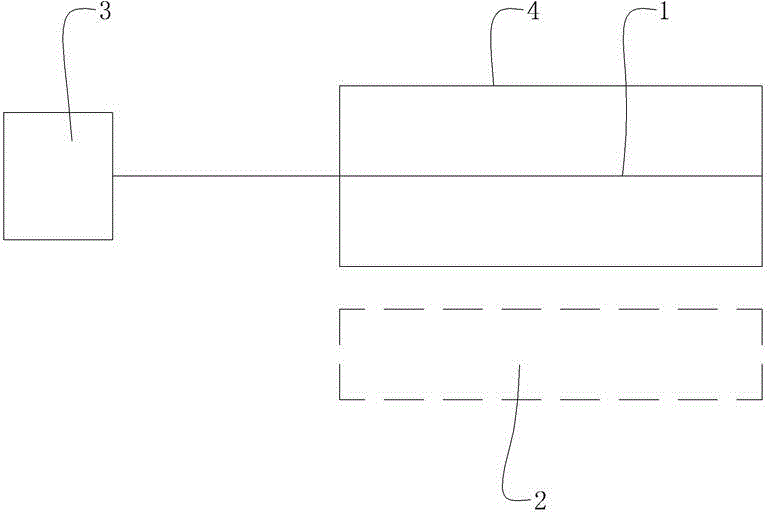
[0044] The coupled negative ion generator of this embodiment is basically the same as the first embodiment, and the difference from the first embodiment is as follows: figure 2 Shown:
[0045] The active discharge body 1 is a conductive straight line passing through the geometric center of the solid insulating medium 4. In this embodiment, the solid insulating medium 4 uses a PVC tube, the active discharge body 1 (discharge tip) in the PVC tube is changed from a carbon brush to a conductive straight line that penetrates the PVC tube, and the negative high voltage generator 3 supplies the battery with an output voltage of 3.7V. -6000V, PVC pipe is completely insulated and closed. The experimental results are shown in Table 2:
[0046] Table 2
[0047] Time-second
Embodiment 3
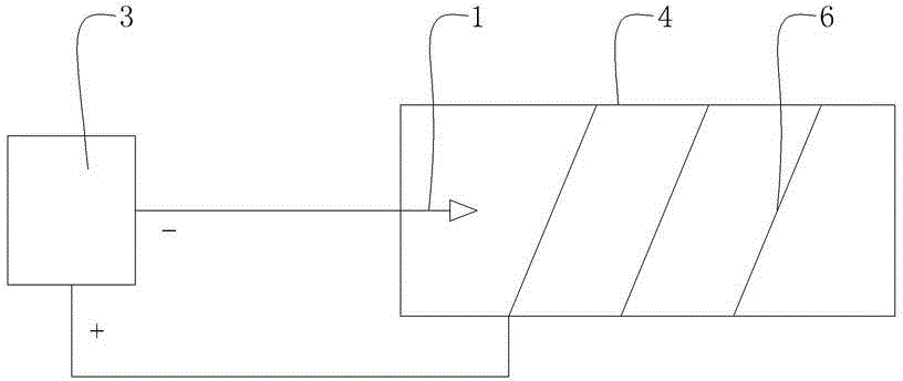
[0049] The coupled negative ion generator of this embodiment is basically the same as the first embodiment, and the difference from the first embodiment is as follows: image 3 Shown:
[0050] 1) Negative high voltage generator 3 is powered by AC 220V power supply, output voltage is -11000V, and output power is not less than 5W;
[0051] 2) A sheathed insulated wire 6 is spirally wound on the outer surface of the PVC pipe at an interval of 50 mm, and one end is connected to the ground terminal of the negative high voltage generator 3.
[0052] The voltage to the ground of the square pure cotton cloth and the voltage to the ground terminal of the negative high voltage generator 3 were measured with a digital multimeter, and they were all 0V.
[0053] Repeat the experiment of Example 1, and the results are shown in Table 3:
[0054] table 3
[0055] Time-second
PUM
 Abstract
Description
Claims
Application Information
 - R&D
- Intellectual Property
- Life Sciences
- Materials
- Tech Scout
- Unparalleled Data Quality
- Higher Quality Content
- 60% Fewer Hallucinations
Browse by: Latest US Patents, China's latest patents, Technical Efficacy Thesaurus, Application Domain, Technology Topic, Popular Technical Reports.
© 2025 PatSnap. All rights reserved.Legal|Privacy policy|Modern Slavery Act Transparency Statement|Sitemap|About US| Contact US: help@patsnap.com


