Ventilator and power control method and system thereof

A power control and ventilator technology, applied in control/regulation systems, respirators, instruments, etc., can solve the problems of increased power consumption, unfavorable energy saving, large size of the ventilator, etc., to reduce requirements, save energy consumption, reduce volume effect

Active Publication Date: 2017-10-20
BMC MEDICAL
View PDF16 Cites 0 Cited by
  • Summary
  • Abstract
  • Description
  • Claims
  • Application Information

AI Technical Summary

Problems solved by technology

However, such a power supply will increase power loss, which is not conducive to energy saving, and will also make the volume of the ventilator larger, which is not conducive to the overall structure of the ventilator meeting the design requirements of compactness

Method used


Image

  • Ventilator and power control method and system thereof
  • Ventilator and power control method and system thereof
  • Ventilator and power control method and system thereof

Examples


Embodiment Construction

[0023] The implementation of the present invention will be described in detail below in conjunction with the accompanying drawings and examples, so as to fully understand and implement the implementation process of how to apply technical means to solve technical problems and achieve corresponding technical effects in the present invention. The embodiments of the present application and the various features in the embodiments can be combined with each other under the premise of no conflict, and the formed technical solutions are all within the protection scope of the present invention.

[0024] Additionally, the steps shown in the flowcharts of the figures may be performed in a computer system, such as a set of computer-executable instructions. Also, although a logical order is shown in the flowcharts, in some cases the steps shown or described may be performed in an order different from that shown or described herein.

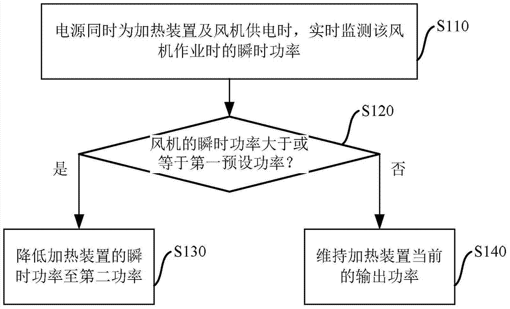
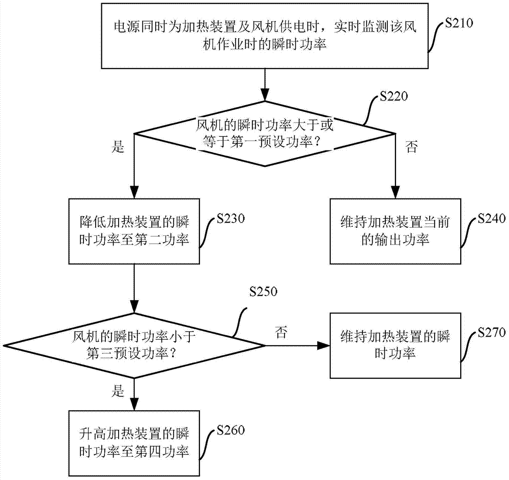
[0025] In order to solve the problem that the heating dev...


PUM


Abstract

The invention discloses a method for controlling the power of a ventilator. The ventilator includes a power supply, a heating device and a fan. ; comparing the instantaneous power of the fan with a first preset power; when the instantaneous power of the fan is greater than or equal to the first preset power, reduce the instantaneous power of the heating device to a second power. The embodiment of the present invention reduces the requirement on the total power of the power supply and saves energy consumption by reducing the instantaneous power consumption of the heating device to meet the instantaneous power required by the instantaneous acceleration of the fan under the working state of the instantaneous acceleration of the fan. The use of a low-power power supply also reduces the volume of the entire ventilator, laying the foundation for the development of further miniaturization of the ventilator.

Description

technical field [0001] The invention relates to a breathing apparatus, in particular to a ventilator and a power control method and system thereof. Background technique [0002] At present, ventilators all have the function of humidifying and pressurizing the flowing gas (such as air) in the breathing tube. There is a heating device inside the ventilator. After the heating device continuously heats the water (or other aqueous solution) in the water tank, the gas will become humid when it flows through the water surface, and the gas will be heated at the same time, so that the user Bring a more comfortable experience. The inside of the ventilator is also provided with a fan, which can suck external air into the ventilator and at the same time apply a certain pressure to the gas entering the breathing tube, which helps to further enhance the use effect. When the user suffers from respiratory stagnation, the fan can further increase the pressure of the gas entering the ventil...

Claims


Application Information

Patent Timeline
Patent Type & Authority Patents(China)
IPC IPC(8): A61M16/00G05F1/66
Inventor 苏厚城庄志
Owner BMC MEDICAL
Why Eureka
Try Eureka