
Plate heat exchanger having sealed construction

A technology of plate heat exchanger and heat exchange plate, which is applied in the direction of indirect heat exchanger, heat exchanger type, heat exchanger shell, etc., and can solve problems such as heat exchanger leakage

Inactive Publication Date: 2015-07-29
SGL CARBON SE
View PDF9 Cites 0 Cited by
  • Summary
  • Abstract
  • Description
  • Claims
  • Application Information

AI Technical Summary

Problems solved by technology

[0014] The structural configuration of pressure parts in commercially available gasketed plate heat exchangers, in particular pressure parts comprising plates based on graphite-containing or ceramic materials such as graphite, silicon carbide or fiber-reinforced ceramic materials, is suitable only to a limited extent. Larger models in the range, because when the size of the structure increases, especially when the plate width and / or plate length increase, the bending of the frame plate increases in the critical area of ​​the seal heat exchanger and therefore in the heat exchanger possible leak

Method used


Image

  • Plate heat exchanger having sealed construction
  • Plate heat exchanger having sealed construction
  • Plate heat exchanger having sealed construction

Examples


Embodiment Construction

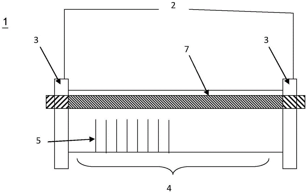
[0051] figure 1 A plate heat exchanger ( 1 ) according to the invention comprising a frame body consisting of two frame plates ( 3 ) is shown. A plate stack (4) of heat exchange plates is arranged between the frame plates (3). Also shown is the force applying means (7).

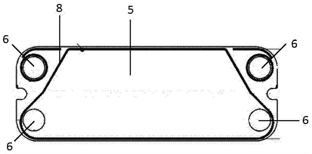
[0052] figure 2 The profile of the heat exchange plates ( 5 ) of the plate stack ( 4 ) (not shown) is shown, including means 6 for feeding and discharging fluid medium and sealing means 8 . It can be seen that the sealing means (8) separate the feed means and the discharge means (6) from each other in a sealed manner.

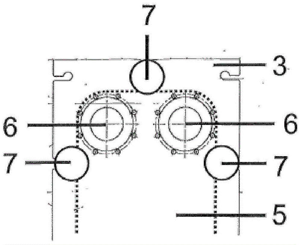
[0053] image 3 The outlines of the frame plate (3) and the heat exchange plate (5) are shown as well as the two devices (6) for feeding and discharging the fluid medium and the three force applying devices (7) indicated by black circles. It can be seen how the center of gravity of the force application surface in all force application devices is outside the area created by the linear p...


PUM


Abstract

The invention relates to a sealed plate heat exchanger (1), comprising a frame body (2) comprising two frame plates (3), between which a plate stack (4) comprising a plurality of heat-exchange plates (5) is arranged, means for feeding and leading away (6) the fluids that flow through the intermediate space between the heat-exchange plates (5) and exchange heat, means for applying force (7) to the frame plates (3), by means of which a pressure can be applied to the plate stack (4), and means for sealing (8) between the heat-exchange plates (5) of the plate stack (4). The center of area of the area of the force application to the frame plate (3) lies within the area that results from a linear projection of the area of the plate stack (4) onto the frame plate (3).

Description

technical field [0001] The invention relates to a gasketed plate heat exchanger comprising: a frame body consisting of two frame plates between which a plate stack of several heat exchange plates is arranged; feed and discharge means for a heat exchange fluid flowing through the spaces between the heat exchange plates; and means for applying a force to the frame plates, by means of which pressure can be exerted on the plate stack. Background technique [0002] A plate heat exchanger consists of a stack of heat exchange plates between which heat transfer takes place. These plates are usually profiled or provided with flow channels and through-openings for the medium. [0003] With plate heat exchangers, a basic distinction can be made between designs without gaskets and designs with gaskets. In the gasket-less configuration, the space between the plates is filled with rigidly connected plates, for example by welding, soldering or fusion techniques. [0004] In gasketed des...

Claims


Application Information

Patent Timeline
Patent Type & Authority Applications(China)
IPC IPC(8): F28F3/08F28F3/10F28F21/02F28F21/04
CPCF28F3/083F28F21/04F28F21/02F28F3/10F28D9/0093F28F9/005
Inventor 马库斯·弗兰兹克里斯托弗·科赫维尔纳·施瓦茨巴特罗伯特·豪泽
Owner SGL CARBON SE
Learn More