
Skate rack and manufacturing method

A manufacturing method and technology of skates, applied in the direction of skates, skating parts, sports accessories, etc., can solve the problems of poor sliding effect, unstable quality, short service life, etc., and achieve low deformation and scrap rate, light weight, self-lubricating good sex effect

Active Publication Date: 2016-09-28
TONGXIANG BONNY SCI & TECH COMPOSITE
View PDF5 Cites 0 Cited by
  • Summary
  • Abstract
  • Description
  • Claims
  • Application Information

AI Technical Summary

Problems solved by technology

[0006] The object of the present invention is to provide a skate rack that is easy to make, strong, Skate rack with strong durability and stable quality and manufacturing method

Method used


Image

  • Skate rack and manufacturing method
  • Skate rack and manufacturing method
  • Skate rack and manufacturing method

Examples


Embodiment 1

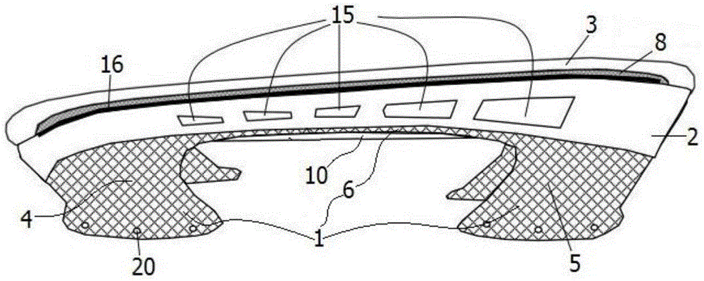
[0063] Such as figure 1 The illustrated embodiment is a skate rack, comprising a sole support base 1, a strip-shaped vertical plate 2 that is arranged on the sole support base and runs through the front and rear ends of the lower surface of the sole support base, and an ice blade 3 connected with the strip-shaped vertical plate; The support seat includes a front sole support seat 4, a rear sole support seat 5 and a connecting strip 6 connecting the front sole support seat, the rear sole support seat and arching downwards; the front sole support seat and the rear sole support seat are all open at the upper end And the cross-sectional area gradually increases from bottom to top in a cylindrical shape, the rear part of the front sole support seat is provided with an opening, the front part of the rear sole support seat is provided with an opening, and the height of the upper end surface of the front sole support seat increases gradually from front to back. The upper end surface o...

Embodiment 2

[0090] Embodiment 2 includes all structures and steps in Embodiment 1, and uses the following steps to replace step 215 in Embodiment 1:

[0091] Paste and connect the preformed body of the front sole support seat, the preform body of the rear sole support seat and the preform body of the connecting strip, and separate the openings of the preform body of the front sole support seat and the preform body of the rear sole support seat with ultra-thin glass fiber cloth. Wrap to obtain the sole support seat preform; surround the shoe sole support seat preform with a glass fiber material with a width of 1.4cm.

[0092] Use the following steps to replace step 211 in Embodiment 1:

[0093] Paste the glass fiber material layer by layer on the front shoe sole support preform which has the same shape as the front shoe sole support to obtain the front shoe sole support preform; put the front shoe sole support preform into a sealed bag to evacuate, Make the layers of the yarn material mor...


PUM


Abstract

The invention discloses a skating shoe frame and a manufacturing method. The skating shoe frame comprises shoe sole support seats, a strip-shaped vertical plate and an ice skate blade connected with the strip-shaped vertical plate, wherein the strip-shaped vertical plate is arranged on the shoe sole support seats and penetrates through the front and rear ends of lower surfaces of the shoe sole support seats; the shoe sole support seats comprise a front shoe sole support seat, a rear shoe sole support seat and a connecting strip which is used for connecting the front shoe sole support seat and the rear shoe sole support seat and is arched downwards; the front shoe sole support seat and the rear shoe sole support seat are barrel-shaped, upper ends of the front shoe sole support seat and the rear shoe sole support seat are open, cross sectional areas of the front shoe sole support seat and the rear shoe sole support seat are gradually increased from bottom to top, an opening is formed in the rear part of the front shoe sole support seat, an opening is formed in the front part of the rear shoe sole support seat, and the height of the upper end surface of the front shoe sole support seat is gradually increased from front to back. The skating shoe frame and the manufacturing method have the characteristics of simple manufacturing process, light weight, high elasticity and flexibility, small friction coefficient, high water absorptivity, stable quality and long service life.

Description

technical field [0001] The invention relates to the technical field of sporting goods, in particular to a skate rack with good durability, capable of improving instantaneous impact resistance, long service life and good dexterity, and a manufacturing method thereof. Background technique [0002] Typical skate racks are injection molded nylon or fabricated from fiberglass or fiberglass. [0003] Skate racks made of nylon injection are heavy and insufficient in hardness; when athletes are exercising, their elasticity is relatively poor, and the sliding effect is not good; they are easy to break, have poor durability, and have a short service life. [0004] Skate racks made of fiberglass or fiberglass are more difficult and time-consuming to manufacture due to their complexity; and the quality is unstable, prone to problems such as yarn jamming, material shortage, inward folding or internal breakage. [0005] Chinese Patent Authorization Publication No.: CN103990265A, authoriz...

Claims


Application Information

Patent Timeline
Patent Type & Authority Patents(China)
IPC IPC(8): A63C1/30A63C1/42A63C3/04
Inventor 洪硕宏
Owner TONGXIANG BONNY SCI & TECH COMPOSITE
Learn More