
Walking beam furnace walking beam original point calibration method

A calibration method and walking beam technology, applied in lighting and heating equipment, furnaces, furnace components, etc., can solve problems such as calibration errors, unfamiliar modified values, affecting normal production, etc., achieving high accuracy and solving calibration calculation errors. , The effect of reducing downtime maintenance time

Active Publication Date: 2015-07-22
BEIJING BESTPOWER INTELCONTROL TECH CO LTD
View PDF5 Cites 1 Cited by
  • Summary
  • Abstract
  • Description
  • Claims
  • Application Information

AI Technical Summary

Problems solved by technology

However, when the displacement sensor is damaged, due to the slight difference in the mechanical installation position, the slight difference in the accuracy of the displacement sensor, etc., and the physical position of the origin initially calibrated, it cannot be accurately determined, and the electrical maintenance personnel in the factory will not be able to accurately determine the reference origin and displacement in the program. The calculated modification value is unfamiliar, which makes the calibration process of the walking beam origin more cumbersome and may lead to calibration errors or inaccuracies
In addition, if the displacement sensor fixed on the walking beam is damaged during the normal production process, the reference origin may not be calibrated quickly, which will affect the normal production
At the same time, when the calibration is carried out under the high temperature of the furnace, the steel position of the walking beam support through visual inspection is not accurate

Method used


Image

  • Walking beam furnace walking beam original point calibration method
  • Walking beam furnace walking beam original point calibration method
  • Walking beam furnace walking beam original point calibration method

Examples


Embodiment Construction

[0015] Specific embodiments of the present invention will be described in detail below with reference to the accompanying drawings.

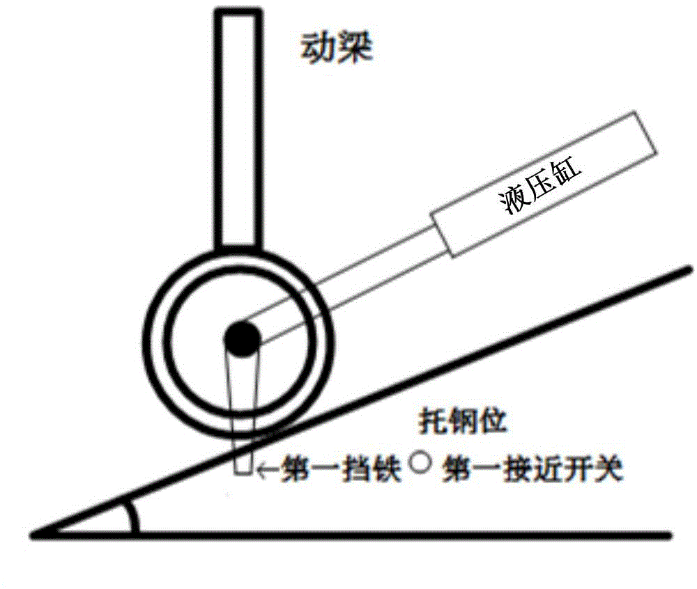
[0016] figure 1 It shows the first stop iron on the lifting hydraulic cylinder of the walking beam and the first proximity switch fixed at the supporting steel position. Wherein, the first iron stopper is installed on one side of the movable axle of the hydraulic cylinder, and the first proximity switch is installed on the position where the walking beam stops at the supporting steel position.

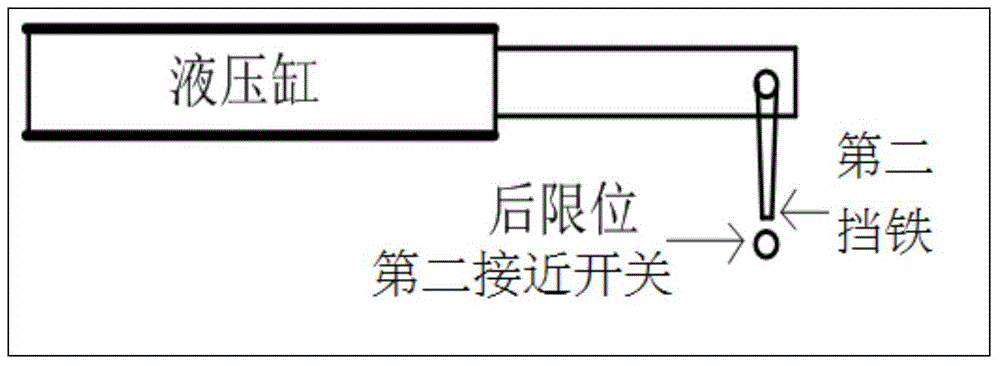
[0017] figure 2 Shown is the second stopper on the horizontal hydraulic cylinder of the walking beam and the second proximity switch fixed at the rear limit. Wherein, the second iron stopper is installed on the telescopic side of the hydraulic cylinder, and the second proximity switch is installed at the position where the walking beam stops at the rear limit position.

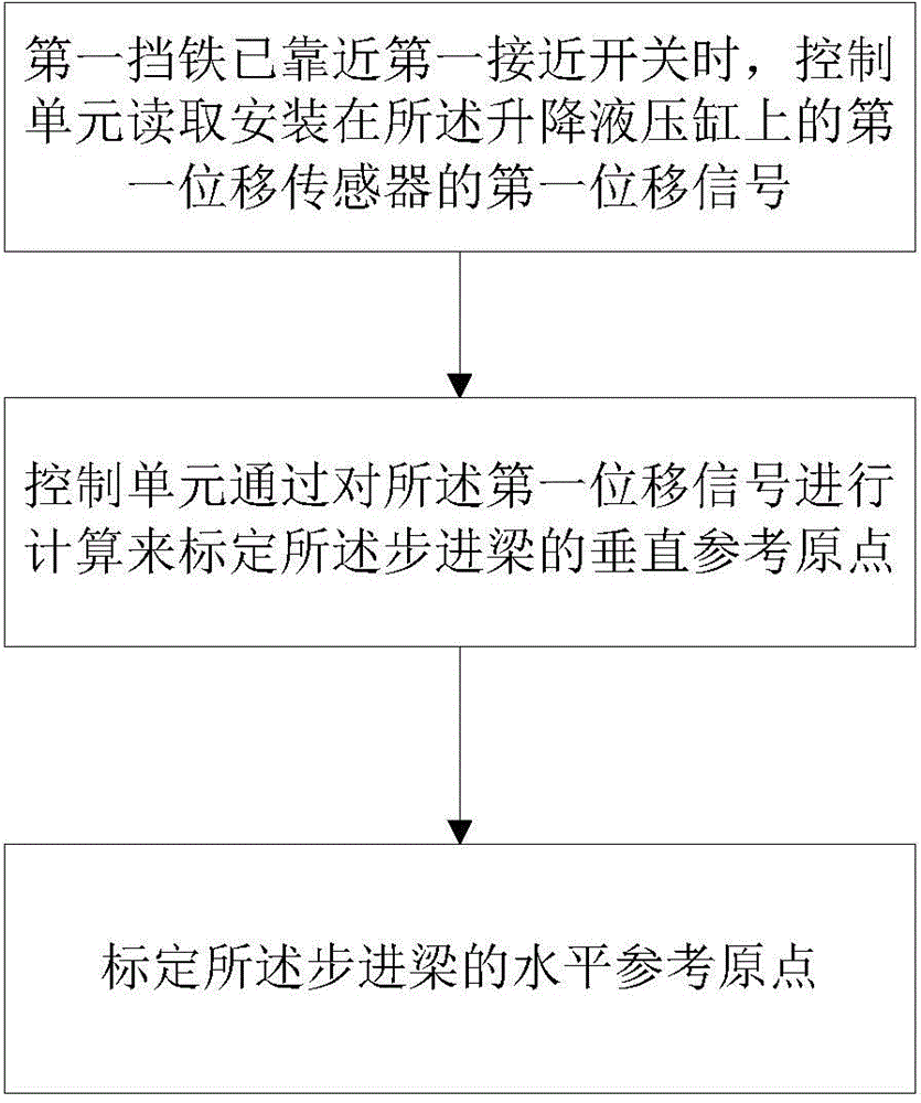
[0018] image 3 A flowchart indicating an embodiment of a method for calibratin...


PUM


Abstract

The invention provides a walking beam furnace walking beam original point calibration method. The method comprises the steps that (a) when a first proximity switch fixed to the portion, stopping on a steel supporting place, of a lifting hydraulic cylinder judges that first stop iron fixed to the movable portion of the lifting hydraulic cylinder is close to the first proximity switch, a perpendicular sensing signal is output to a control unit, and the control unit reads a first displacement signal of a first displacement sensor installed on the lifting hydraulic cylinder after receiving the perpendicular sensing signal; (b), the control unit computes the first displacement signal to calibrate the perpendicular reference original point of a walking beam. According to the calibration method, the reference original point can be calibrated rapidly, the accuracy is high, and the problem that electrical maintenance personnel of a factory is unfamiliar with original point calibration and program computing, so that calibration computing errors are produced, or long time is needed for completing calibration is solved.

Description

technical field [0001] The invention relates to a method for calibrating the origin of a walking beam of a walking heating furnace. Background technique [0002] In the walking furnace equipment, the walking beam is one of the very important equipment. For an ordinary 120t / h walking furnace, the process requires the walking beam to step 250mm per step. After 86 steps, the total error allowable range is one thousandth (about 20mm), so the displacement of the walking beam Calculations require great precision. At the same time, due to the need to reserve a certain deceleration buffer zone for the descending and retreating of the walking beam, or the need to adjust the step cycle or step curve, and the fact that it is difficult for the oil cylinder to stop at the physical origin, the reference point is used as the reference point for each step of the walking beam. The origin of each run is the commonly used walking beam positioning method. The displacement calculation of the ...

Claims


Application Information

Patent Timeline
IPC IPC(8): F27D3/12B65G25/02B65G43/00
Inventor 李怡孙丽杨天智亢晓嵘宋洁姜智伟张一凡王树松
Owner BEIJING BESTPOWER INTELCONTROL TECH CO LTD
Learn More