
Electric furnace for waste mercury and catalyst mercury recovery

A waste mercury catalyst and electric furnace technology, applied in the direction of improving process efficiency, etc., can solve the problems of small equipment capacity, low production efficiency, agglomeration, etc., and achieve the effects of uniform heating, improved service life and furnace temperature uniformity

Active Publication Date: 2015-07-22
XINJIANG CORPS MODERN GREEN CHLOR ALKALI CHEM ENG RES CENT LTD
View PDF6 Cites 4 Cited by
  • Summary
  • Abstract
  • Description
  • Claims
  • Application Information

AI Technical Summary

Problems solved by technology

[0003] The object of the present invention is to provide a kind of electric furnace that is used for waste mercury catalyst mercury recovery, further say to provide a kind of large-capacity electric furnace that is used for waste catalyst mercury recovery, solve the problem of small equipment capacity, low production efficiency, agglomeration, Automate operations

Method used


Image

  • Electric furnace for waste mercury and catalyst mercury recovery
  • Electric furnace for waste mercury and catalyst mercury recovery
  • Electric furnace for waste mercury and catalyst mercury recovery

Examples


Embodiment 1

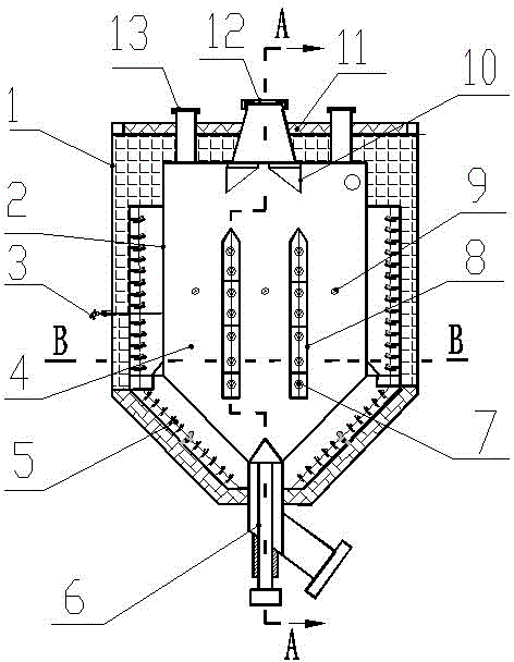
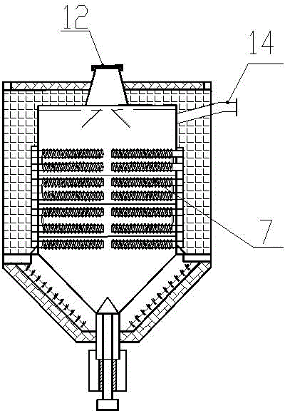
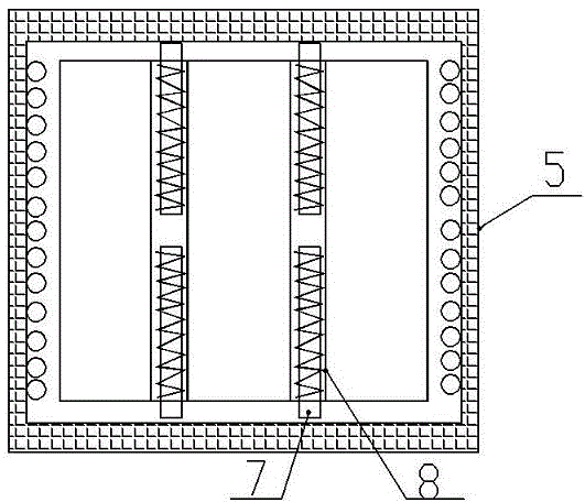
[0018] Refer to the attached figure 1 - 3. The electric furnace mainly includes a furnace cover 11, a furnace body 1, a furnace tank 2, a heating element, and a heating control system. The furnace tank 2 is located inside the furnace body 1, the outer heating element 5 is located outside the furnace tank 2, and the inner heating element 7 Arranged in the heating chamber 8 in the furnace tank 2, the heating control system adjusts the heating power of the inner heating element 7 and the outer heating element 5 according to the temperature in the furnace tank 2, the temperature of the electric furnace is controlled at 750 °C, and the temperature control accuracy is ±1 °C .

[0019] In the embodiment of the present invention, the furnace body 1 is composed of an outer shell, a furnace lining, and an external heating element support body. The outer shell is made of square steel and thin common steel plate, and the load-bearing shell adopts a steel frame, which has sufficient streng...

Embodiment 2

[0027] The heating control system adjusts the heating power of the inner heating element 7 and the outer heating element 5 according to the temperature inside the furnace tank 2. The temperature of the electric furnace is controlled at 550°C, and the temperature control accuracy is ±1°C; the heating chamber 8 is evenly distributed into 2 widths and set to 200mm The small chamber 4, the lower part of the small chamber 4 in the furnace tank 2 is the same cone, and the small chamber 4 and the upper part of the furnace tank 2 are provided with a space of 200mm; the inner heating element 7 is divided into 7 groups of heating bodies that can be independently disassembled 7 layers, the inner heating element 7 is in the form of resistance wire wrapped on the corundum porcelain tube; there is one main feeding port and two auxiliary feeding ports on the furnace cover.

Embodiment 3

[0029] The heating control system adjusts the heating power of the inner heating element 7 and the outer heating element 5 according to the temperature inside the furnace tank 2. The temperature of the electric furnace is controlled at 800°C, and the temperature control accuracy is ±1°C; the heating chamber 8 is evenly distributed into 4 or more widths Set the small chamber 4 of 400mm, the lower part of the small chamber 4 in the furnace tank 2 is the same cone, and the small chamber 4 and the upper part of the furnace tank 2 are provided with a space of 400mm; the inner heating element 7 is divided into 4 or more groups and can be dismantled independently The installed heating body is divided into 4 or more layers up and down, and the inner heating element 7 is in the form of a resistance wire wound on a silicon carbide rod or a silicon molybdenum rod; the furnace cover 11 is provided with 1 main feeding port and 6 auxiliary feeding ports .

[0030] According to the electric ...


PUM


Abstract

The invention provides an electric furnace for waste mercury and catalyst mercury recovery and solves the problems of low capacity and low yield of equipment for recovering waste mercury and catalyst mercury by adopting the electric furnace. The invention provides the high-capacity electric furnace for the waste mercury and catalyst mercury recovery, which comprises a furnace cover, a furnace body, a furnace tank, a material distributor, heating elements, a heating control system and a discharge device, wherein a main feeding inlet and auxiliary feeding inlets are formed in the furnace cover; the heating elements comprise an outer heating element and an inner heating element; the furnace tank is a closed container and is positioned in the furnace body; the main feeding inlet, the auxiliary feeding inlets and a gas outlet are formed in the upper part of the furnace tank; the material distributor is arranged at the lower part of the main feeding inlet; the lower part of the furnace tank is a cone, the discharge device is arranged at the lower part of the furnace tank, temperature measuring elements are arranged outside and inside the furnace tank and connected with the heating control system through conducting wires, a plurality of heating chambers are formed in the middle area of the furnace tank, the furnace tank is divided into a plurality of small bins, and all the small bins share the cone part of the furnace tank.

Description

technical field [0001] The invention relates to a chemical equipment device for recycling waste mercury catalyst, in particular to an electric furnace for recycling waste mercury catalyst mercury. Background technique [0002] Mercury chloride catalyst is used as catalyst in the production of polyvinyl chloride by calcium carbide method. After a certain period of time, it is discharged from the converter. It is called waste catalyst. Since it contains a certain amount of mercury chloride, it is a hazardous waste and cannot be discarded at will. , and mercury is an increasingly scarce resource. At present, there are three ways to deal with waste mercury catalysts. One is to recover the mercury in it by fire recovery, and the mercury element is reused after treatment; the first is to use oxygen-controlled dry distillation. The first is to heat and directly recover the mercury chloride in the waste catalyst under the condition of isolating the air; the third is to use chemical ...

Claims


Application Information

Patent Timeline
Patent Type & Authority Applications(China)
IPC IPC(8): C22B43/00C22B7/00
CPCY02P10/20
Inventor 李全胜李朝阳李永宏王银亮李自兵张学鲁陈财来徐勇
Owner XINJIANG CORPS MODERN GREEN CHLOR ALKALI CHEM ENG RES CENT LTD
Learn More