Torque limit control

A torque and torque load technology, applied in the field of limiting the torque presented by hydraulic tools, can solve problems such as mechanical failures

Inactive Publication Date: 2015-07-08
CATERPILLAR PAVING PROD INC
View PDF6 Cites 2 Cited by
  • Summary
  • Abstract
  • Description
  • Claims
  • Application Information

AI Technical Summary

Problems solved by technology

The combined torque fed back to the prime mover through the PTO can cause mechanical failure of key components of the PTO or prime mover's gear train

Method used


Image

  • Torque limit control
  • Torque limit control
  • Torque limit control

Examples


Embodiment Construction

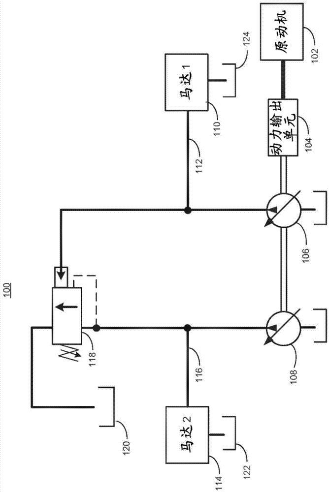
[0014] figure 1 is a simplified schematic view of a first embodiment 100 of a torque limit control apparatus. A prime mover 102 , such as a diesel engine, may mechanically drive a power take-off (PTO) unit 104 . The PTO 104 in turn may drive a first hydraulic pump 106 and a second hydraulic pump 108 . The first hydraulic pump 106 can drive the first hydraulic motor 110 through the first hydraulic circuit 112 . The first hydraulic circuit 112 may terminate in a reservoir 124 which may be coupled to the hydraulic pump 106 in a known manner. In one embodiment, the first motor 110 can drive a steering (steering) unit in the vehicle.

[0015] The second hydraulic pump 108 can drive the second hydraulic motor 114 through the second hydraulic circuit 116 and the reservoir 122 . In various exemplary embodiments, reservoir 122 and reservoir 124 may be the same reservoir associated with pumps 106 and 108 . In an exemplary embodiment, the second hydraulic motor 114 may drive a compa...


PUM


Abstract

A prime mover transfers power to a separate hydraulic circuits via a power take off (PTO). In some situations, a peak torque demand in one of the hydraulic circuits may cause the total torque of all hydraulic circuits to exceed a rated torque at the PTO. An apparatus measures hydraulic fluid pressure in a first hydraulic circuit and adjusts the hydraulic fluid pressure in a second hydraulic circuit. Because pressure is directly correlated to torque at a pump, by adjusting the pressure in the second circuit based on the current pressure in the first hydraulic circuit, the total torque may be capped below the maximum torque rating at the PTO. The first hydraulic circuit may have a higher priority function, such as steering, compared to that of the second hydraulic circuit which may, for example, power a tool.

Description

technical field [0001] The present invention relates to hydraulic tools, and more particularly to (a method of) limiting the torque exhibited by hydraulic tools. Background technique [0002] A power take off (PTO) unit may be used to transfer power between a prime mover, such as a diesel engine, and one or more hydraulic pumps. In applications using two or more hydraulic pumps, the total torque of the combined hydraulic pumps may exceed the torque rating of the PTO device and / or prime mover, especially during transient conditions. This can lead to catastrophic failure of the prime mover. [0003] An example is a road compactor that utilizes one hydraulic pump to drive the steering circuit and another hydraulic pump to drive the compactor unit. Activation of the compactor unit causes very high momentary pressures in the hydraulic circuit of the compactor hydraulic pump. If this occurs while a steering maneuver is taking place, such as over a steep slope, the resulting ove...

Claims


Application Information

Patent Timeline
IPC IPC(8): F15B11/00F15B13/02
CPCF15B13/021F15B13/06F02D29/04E02F9/2242F02B3/06F15B18/00F15B2211/20523F15B2211/20576F15B2211/50518F15B2211/5157F15B2211/528F16H61/12F16H61/4017F16H61/4148
Inventor J·A·阿尔德马E·恩格尔曼
Owner CATERPILLAR PAVING PROD INC
Why Eureka
Try Eureka