
An ultrasonic spray pyrolytic coating device

A technology of ultrasonic spray pyrolysis and coating device, which is applied in the direction of liquid chemical plating, metal material coating process, coating, etc., and can solve the problems of limiting the continuous operation of ultrasonic sprayers, large heat generation of ultrasonic sprayers, and long coating time, etc. Achieve the effects of product area and thickness control, ingenious structural design, and convenient operation

Active Publication Date: 2017-05-24
重庆复源新材料科技有限公司
View PDF9 Cites 2 Cited by
  • Summary
  • Abstract
  • Description
  • Claims
  • Application Information

AI Technical Summary

Problems solved by technology

Using the XY movable thermal platform disclosed in the invention patent application of CN103757613A can improve the size and uniformity of the film prepared by ultrasonic spray pyrolysis to a certain extent, but the larger the film size, the longer the coating time required
Due to long-time work, the ultrasonic nebulizer generates too much heat, which is easy to cause damage to the equipment
Although some ultrasonic nebulizers on the market are equipped with an over-temperature protection function, it also limits the continuous operation of the ultrasonic nebulizer
In addition, after the ultrasonic spray coating equipment works for a long time, the mist is easy to condense into water droplets at the pipe and outlet, once it drops on the surface of the substrate, it will cause serious damage to the film

Method used


Image

  • An ultrasonic spray pyrolytic coating device
  • An ultrasonic spray pyrolytic coating device
  • An ultrasonic spray pyrolytic coating device

Examples


Embodiment 1

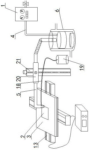
[0016] Embodiment 1: as figure 1 As shown, an ultrasonic spray pyrolysis coating device includes a gas cabinet 1, an ultrasonic atomization device, a spray head, and a heating table 3 with a substrate 2, and the gas cabinet 1 communicates with the ultrasonic atomization device through an air inlet pipe 4 , the ultrasonic atomization device communicates with the spray head through the pipeline 5, the spray head is located above the heating table 3 and corresponds to the heating table 3, an XY mobile platform 13 is arranged below the heating table 3, and the ultrasonic A cooling device is arranged outside the atomizing device.

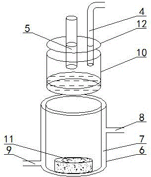
[0017] Such as figure 2 As shown, the cooling device of the present invention includes a double-layer cup body cooling barrel 6, a cooling chamber 7 is arranged between the double-layer cup bodies, and a cooling chamber communicated with the cooling chamber 7 is respectively provided at the upper and lower parts of the cooling barrel 6. Cooling water ...


PUM


Abstract

The invention discloses an ultrasound spray pyrolysis film coating device. The ultrasound spray pyrolysis film coating device comprises a gas cabinet (1), an ultrasound atomizing device, a spray head and a heating platform (3) with a base plate (2). The ultrasound spray pyrolysis film coating device is characterized in that the gas cabinet (1) is communicated with the ultrasound atomizing device through a gas inlet pipe (4), the ultrasound atomizing device is communicated with the spray head through a pipeline (5), the spray head is located above the heating platform (3) and corresponds to the heating platform (3), an XY moving platform (13) is arranged below the heating platform (3), and a cooling device is arranged outside the ultrasound atomizing device. The ultrasound spray pyrolysis film coating device has the advantages of being ingenious in structural design, convenient to operate and low in cost. By means of the ultrasound spray pyrolysis film coating device, preparing of large films can be conducted for a long time, the area and the thickness of the films can be controlled, the water dropping problem in the film coating process is solved, the yield of the films is increased, and the quality of the films is improved.

Description

technical field [0001] The invention relates to a wet coating device, in particular to an ultrasonic spray pyrolysis coating device. Background technique [0002] Ultrasonic spray pyrolytic coating is a technology that uses ultrasonic waves to hit the liquid to generate mist at the edge of the water column, and uses the carrier gas to transport the mist to the heated substrate to deposit a thin film on the surface of the substrate. It is very suitable for the preparation of zinc oxide, tin oxide, oxide Molybdenum and other thin films. Compared with other wet coating technologies, its advantage is that the film quality is better, and the density of impurities and defects is low; compared with vacuum coating technology, it has the advantages of low cost and large area. After certain improvements, roll-to-roll (Roll-to-roll) -to-Roll) production. However, in the existing ultrasonic spray pyrolysis coating device to prepare thin film materials, most of them use tube furnace or...

Claims


Application Information

Patent Timeline
Patent Type & Authority Patents(China)
IPC IPC(8): C23C18/12
Inventor 程江李璐闫雪莲杨鑫胡荣张晟熙
Owner 重庆复源新材料科技有限公司
Learn More