
Flywheel energy storage propelling device

A flywheel energy storage and propulsion device technology, applied in the direction of launch/drag transmission, etc., can solve technical complexity, equipment reliability, overall size cost, maintenance cost and energy conversion efficiency, frequent replacement of U-shaped sealing strips, steam ejection Problems such as large technical size, to achieve the effect of simple structure, low operating cost, and reduced operational complexity

Active Publication Date: 2015-07-08
葛愉成 +2
View PDF5 Cites 13 Cited by
  • Summary
  • Abstract
  • Description
  • Claims
  • Application Information

AI Technical Summary

Problems solved by technology

However, no matter it is steam catapult or electromagnetic catapult, technical complexity, equipment reliability, overall size, cost, maintenance cost and energy conversion efficiency, etc., have been researched and discussed problems for a long time.
For example, the steam ejection technology has the advantages of large size, high manufacturing cost, low efficiency, many supporting facilities, cumbersome system, high requirements for each link; high use and maintenance costs, frequent and troublesome replacement of U-shaped sealing strips, and high requirements for materials; It needs to consume a lot of fresh water. The United States once considered a steam condensation recovery device for this purpose, but it was finally canceled due to its large size and low efficiency.
Although the electromagnetic catapult is smaller than the steam catapult, the system is very complex and has higher requirements for materials, technology, electromechanical control, maintenance, etc.

Method used

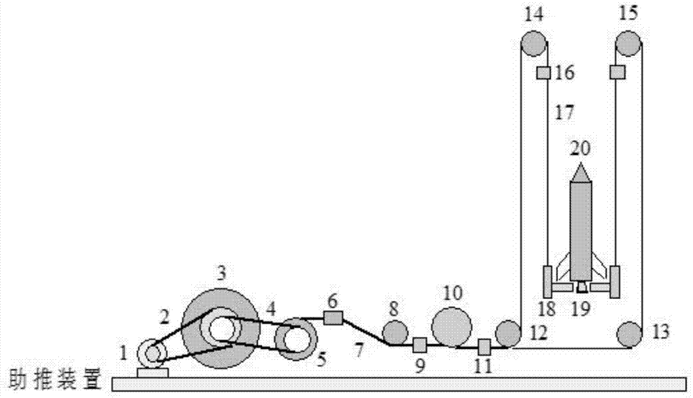
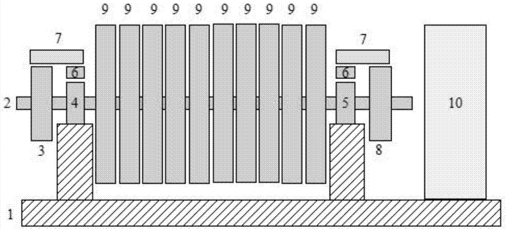

Image

  • Flywheel energy storage propelling device
  • Flywheel energy storage propelling device
  • Flywheel energy storage propelling device

Examples


Embodiment Construction

[0040] The present invention will be further elaborated below in conjunction with accompanying drawing by the mode of specific embodiment:

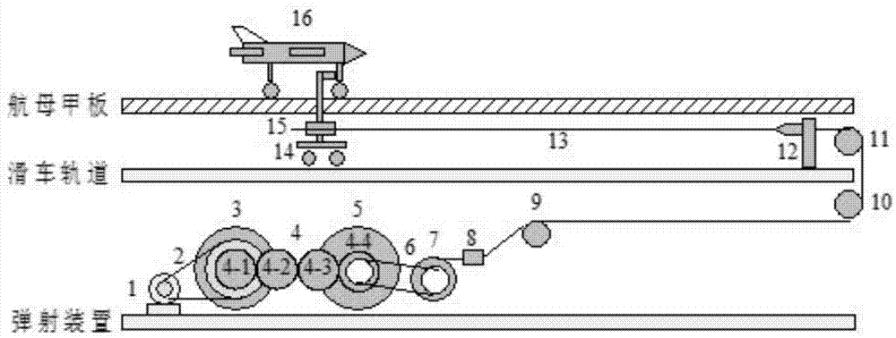
[0041] Such as figure 1 As shown: the motor unit 1 of the propulsion device drives the flywheel 3 to rotate through the transmission device 2, and stores electric energy or other mechanical energy (such as internal combustion engine, steam turbine, etc.) in the flywheel. For aircraft carriers, in order to overcome the influence of additional angular momentum and lateral torque on ship navigation, through gear set 4 (including gears 4-1, 4-2, 4-3, 4-4) or other transmission mechanisms (such as worm, belt ) is coupled with another flywheel 5 that is identical but rotates in the opposite direction. Therefore, the total angular momentum of the energy storage system composed of flywheel 3 and flywheel 5 is 0. When the aircraft needs to be ejected, the energy storage system drives the variable shaft diameter steel cable winding machine 7 to r...


PUM


Abstract

The invention relates to a flywheel energy storage propelling device. The flywheel energy storage propelling device comprises a motor unit, a transmission device, a flywheel energy storing system, an energy releasing device, a guide rope, a pulley block, a tackle and a tackle rail. The flywheel energy storage propelling deice is suitable for ejecting and propelling objects of different mass classes, such as unmanned aerial vehicles, warplanes, early warning airplanes, rockets, guided missiles and the like according to a reserved parameter change curve. The ejection process is controllable, and the changing processes of acceleration, speed, sliding distance and the like can be optimized according to needs and the mass magnitude of the airplanes, the guided missiles or the rockets.

Description

technical field [0001] The invention belongs to propulsion technology, in particular to a propulsion device using a flywheel energy storage system. Background technique [0002] If you want to eject dozens of tons of fighter jets on an aircraft carrier deck runway about 100 meters away at a speed of 200 to 300 kilometers per hour within 3 seconds, you need hundreds of megajoules of energy. It is difficult for a general engine to provide such a large power output in a short period of time. Energy storage methods are usually used, such as using high-temperature steam to store energy, and then transforming the internal energy of the steam into mechanical energy through long-distance cylinders to eject the aircraft; or through supercapacitor energy storage and discharge, or high-speed flywheel energy storage, drive generators to generate electricity, and use linear The current-carrying wire in the motor is stressed in the magnetic field, and the induced electromagnetic repulsio...

Claims


Application Information

Patent Timeline
IPC IPC(8): B64F1/06
Inventor 葛愉成何海萍葛湘洁
Owner 葛愉成
Learn More