A light-load and high-efficiency realization circuit of a dc-dc converter
A DC-DC and converter technology, applied in the field of DC-DC converters, can solve the problems of dead time loss, control circuit loss, external component loss, etc., and achieve the effects of improving efficiency, reducing internal consumption, and high precision
- Summary
- Abstract
- Description
- Claims
- Application Information
AI Technical Summary
Problems solved by technology
Method used
Image
Examples
Embodiment Construction
[0016] The specific embodiments of the present invention will be further described below in conjunction with the accompanying drawings.
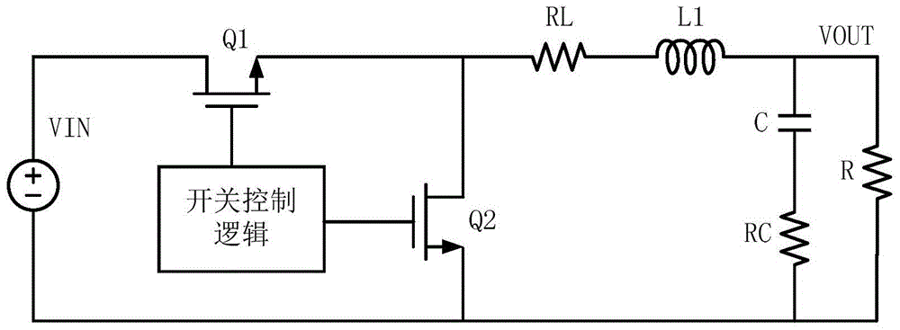
[0017] The core link of the present invention is described here. In a common DC-DC converter, the switch tube is Q1, and its on-resistance is R Q1 . Then the loss when Q1 is turned on can be expressed as:
[0018] P COND_D1 = I OUT 2 *R Q1 *D (1)
[0019] where I OUT refers to the output load current, R Q1 Refers to the on-resistance of the upper tube Q1, and D is the duty cycle.
[0020] The losses driving Q1 (that is, switching losses) can be expressed as:
[0021] P SWITCH =Q G *V IN *F SW =C GS1 *V GS *V IN *F SW (2)
[0022] Among them, CGS1 is the parasitic gate-source capacitance of Q1, VGS is the gate-source voltage when the switch tube is working, FSW is the switching frequency of the switch tube, and VIN is the power supply voltage.
[0023] The loss of the internal circuit P IN Consumption of fixed bias and c...
PUM
 Abstract
Description
Claims
Application Information
 - R&D Engineer
- R&D Manager
- IP Professional
- Industry Leading Data Capabilities
- Powerful AI technology
- Patent DNA Extraction
Browse by: Latest US Patents, China's latest patents, Technical Efficacy Thesaurus, Application Domain, Technology Topic, Popular Technical Reports.
© 2024 PatSnap. All rights reserved.Legal|Privacy policy|Modern Slavery Act Transparency Statement|Sitemap|About US| Contact US: help@patsnap.com


