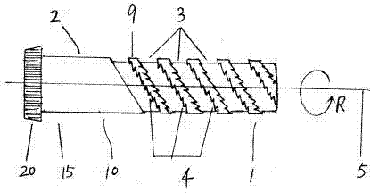
Cotton-picking spindle
A technology for picking cotton and threading, which is applied to picking machines, agricultural machinery and implements, applications, etc., can solve the problem of large impurity content in cotton, and achieve the effect of good cotton doffing operation, reducing friction and reducing friction coefficient.
- Summary
- Abstract
- Description
- Claims
- Application Information
AI Technical Summary
Problems solved by technology
Method used
Image
Examples
Embodiment 1
[0022] Example 1 figure 1 , Figure 4 Shown. The cotton picking spindle of the present invention includes a cotton picking part 1 and a driving part 2. The picking spindle 10 rotates around its axis line, and the driving part 2 is connected with a driving device. The driving part 2 includes a bearing part 15 which is concentric with the longitudinal axis 5 and is supported in a bushing (not shown in the figure) in the spindle lifter. The gear 20 is located at the end of the bearing part 15, and the gear 20 meshes with an auxiliary gear (not shown in the figure) in the spindle picking rod, so that the spindle 10 rotates in the cotton picking direction R around the axis 5. The cotton picking part 1 is provided with at least one continuous spiral groove 3 along the axial direction, and there is a continuous thread protrusion 9 formed by the groove wall of the spiral groove 3. The rotation direction of the thread protrusion 9 is the same as the rotation of the spindle 10 when grabb...
Embodiment 2
[0025] Example 2 such as figure 2 , Image 6 , Figure 7 , Figure 8 Shown. The ingot picking includes a cotton picking part 8 and a driving part. The cotton picking part 8 is provided with at least one continuous spiral groove 6 along the axial direction, and there is a continuous thread protrusion formed by the groove wall of the spiral groove 6. The best range of the helix angle θ of the thread protrusion and the spiral groove 6 is: 10o≤θ≤65o. versus figure 1 The difference is that the cotton picking part 8 is a conical thread; a plurality of hook teeth 7 are provided on the side of the included angle area formed by the side wall and the top surface of the thread protrusion.
[0026] Such as Figure 4 , Figure 5 , Image 6 Shown. The cross-sectional shape of the threaded protrusion can be rectangular, trapezoidal or sawtooth.
Embodiment 3
[0027] Example 3 such as image 3 Shown. The difference from Embodiment 1 is that hook teeth 12 are provided in the spiral groove 11, and no hook teeth are provided on the threaded protrusion 16.
[0028] Such as Picture 9 , Picture 10 Shown. Picture 9 It is a schematic diagram showing that the hook tooth provided by the present invention does not completely destroy the continuity of the top surface of the thread protrusion. Picture 10 It is a schematic diagram of the hook teeth provided in the present invention forming a slit on the top surface where it is located, and at least a part of the slit width γ is less than 1.5 mm.
[0029] In the operation of embodiment 1, the attached gear in the ingot 10 rotates the gear 20 when the cotton is picked, and the gear 20 makes the ingot 10 rotate in the direction R around the axis line 5, when the hook 4 of the threaded protrusion 9 and When cotton sticks, cotton bolls or cotton stalks and other hard objects are in contact, the threa...
PUM
 Abstract
Description
Claims
Application Information
 - R&D
- Intellectual Property
- Life Sciences
- Materials
- Tech Scout
- Unparalleled Data Quality
- Higher Quality Content
- 60% Fewer Hallucinations
Browse by: Latest US Patents, China's latest patents, Technical Efficacy Thesaurus, Application Domain, Technology Topic, Popular Technical Reports.
© 2025 PatSnap. All rights reserved.Legal|Privacy policy|Modern Slavery Act Transparency Statement|Sitemap|About US| Contact US: help@patsnap.com


