
Method for static imbalance test for inertial platform framework

A static unbalance and inertial platform technology, applied in the field of inertial navigation, can solve the problems that the test repeatability and reproducibility are easily affected by human operation, the static unbalance test method cannot meet the requirements, and the test resolution and accuracy cannot be required. , to achieve the effect of eliminating the influence factors of human operation, good repeatability and reproducibility, and accurate testing

Inactive Publication Date: 2015-06-17
FLIGHT AUTOMATIC CONTROL RES INST
View PDF5 Cites 8 Cited by
  • Summary
  • Abstract
  • Description
  • Claims
  • Application Information

AI Technical Summary

Problems solved by technology

The test resolution and accuracy of this method are affected by the static friction torque of the frame. At present, the static unbalance index of the frame requires ≯20g.cm, and the magnitude of the static friction torque of the frame rotation has also reached 20g.cm. The test resolution and accuracy cannot Requirements; At the same time, the dynamometric method is also closely related to the operator's technique, and the test repeatability and reproducibility are easily affected by human operation.
[0004] As the environmental adaptability and precision index requirements of the inertial navigation system are getting higher and higher, the balance accuracy of the inertial platform frame is also getting higher and higher, and the traditional static unbalance measurement method can no longer meet the demand

Method used


Image

  • Method for static imbalance test for inertial platform framework
  • Method for static imbalance test for inertial platform framework
  • Method for static imbalance test for inertial platform framework

Examples


Embodiment

[0034] see Figure 4 , which is a schematic diagram of using the present invention to test the static unbalance of a certain type of inertial platform frame. The specific test process is as follows:

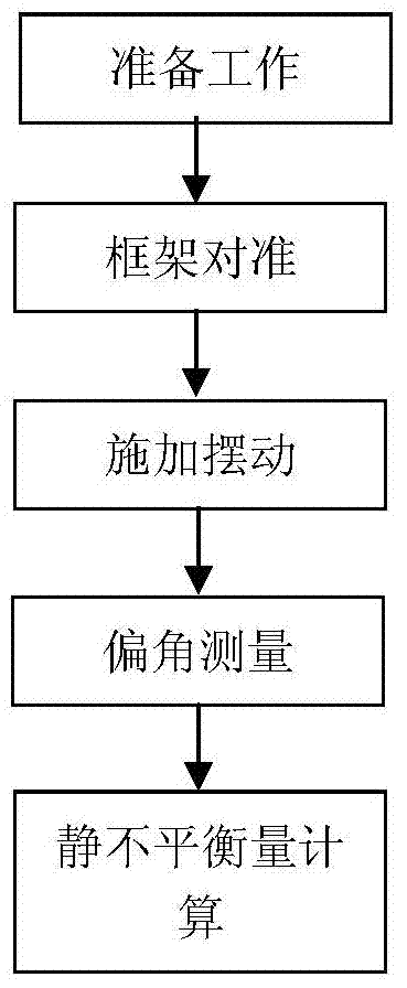
[0035] Step 1, preparation work: build a signal input system 5 and a data acquisition and processing system 6 on the frame to be tested 1;

[0036] Step 2, frame alignment: straighten the frame 1 to be tested to the mechanical zero position;

[0037] Step 3, applying swing: the signal input system 5 applies swing to the frame 1 through the motor 3 as a driving mechanism, and controls the swing frequency to 1.5-2 Hz;

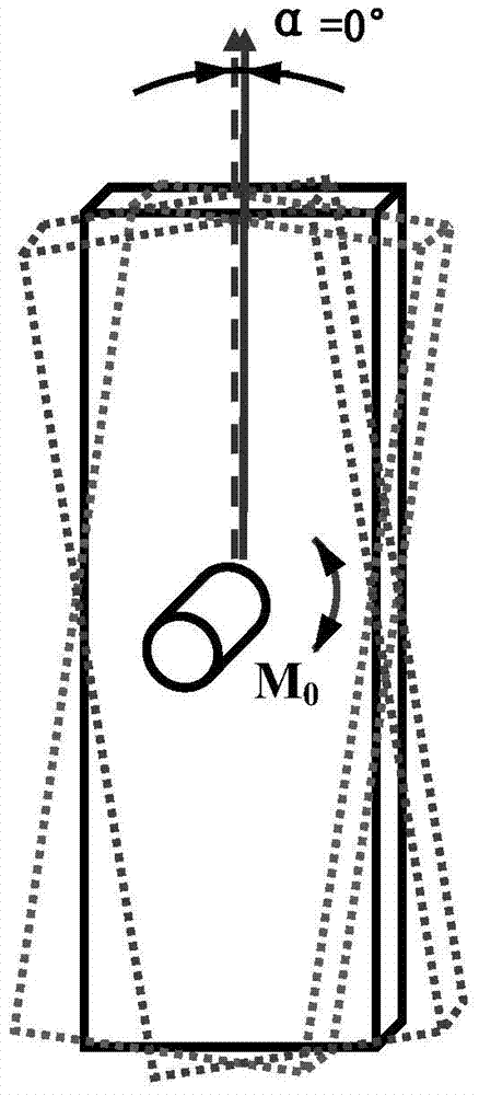
[0038] Step 4, deflection angle measurement: the data of the angle sensor 4 is collected by the data acquisition and processing system 6, and the deflection angle α=11.5° of the frame 1 relative to the mechanical zero position is calculated after the data is processed by signal filtering.

[0039] Step five, static unbalance calculation: based on Calculate the ...


PUM


Abstract

The invention relates to a method for static imbalance test for an inertial platform framework, which belongs to the inertial navigation technology. The method comprises the following steps: 1, preparation work is carried out; 2, framework alignment is carried out; 3, a to-be-tested framework is righted to a mechanical zero; 3, swinging is applied, swinging is applied to the framework via a driving mechanism, and the swinging frequency is controlled; 4, a deflection angle is measured, the swinging center of the framework is found out, and the deflection angle alpha of the swinging center in relative to the mechanical zero is measured; and 5, static imbalance is calculated. The framework rotation static friction torque interference factor existing in an original force measurement method is reduced by a magnitude order, and the test resolution can be improved by a magnitude order; the problem that the original force measurement method is likely to be influenced by manual operation can be solved; the method has the advantages of high test resolution, accurate test, and good repeatability and reproducibility; and demands on improvement of platform framework balance precision by inertial navigation system environmental suitability and accuracy index improvement can be met.

Description

technical field [0001] The invention belongs to the inertial navigation technology and relates to a method for testing the static unbalance of an inertial platform frame. Background technique [0002] The frame inertial platform is the core component of the inertial stabilization system. The inertial platform is mainly composed of an inertial sensor gyroscope, an accelerometer, a set of frames and related circuits. As a constant disturbance moment, the static unbalance of the frame (gimbal) will affect the characteristics of its stability control loop, thereby reducing the navigation accuracy and attitude accuracy of the inertial stabilization system. [0003] At present, the dynamometer method is used to test the static unbalance of the inertial platform frame, which is to select a force-measuring point on the frame, pull the frame to rotate with a hanging weight or a spring dynamometer, and record the force value at which the frame starts to rotate; The difference betwee...

Claims


Application Information

Patent Timeline
Patent Type & Authority Applications(China)
IPC IPC(8): G01M1/16
Inventor 刘行胜照宇叶坤杨以才张宇星
Owner FLIGHT AUTOMATIC CONTROL RES INST
Learn More