Gas constant-flow output feedforward control apparatus and gas constant-flow output feedforward control method

A feedforward control, constant flow technology, applied in the field of feedforward control systems, can solve problems such as large jitter in the collection volume, the upstream pressure cannot be kept constant, and the output value of the actuator is affected, so as to achieve a simple and easy control scheme and avoid measurement Effect of value perturbation or control response lag

Active Publication Date: 2015-06-17
DALIAN INST OF CHEM PHYSICS CHINESE ACAD OF SCI
View PDF5 Cites 3 Cited by
  • Summary
  • Abstract
  • Description
  • Claims
  • Application Information

AI Technical Summary

Problems solved by technology

Among them, the first method requires that the upstream pressure of the device is sufficiently large and constant, but in fact, the saturated vapor pressure of some gases determines that the gaseous pressure cannot be increased infinitely, and, unless the gas storage tank is large enough, as the gas Outflow, the upstream pressure cannot be kept constant, especially when the gas flow rate is large; although the second method can adjust the output pressure in a closed loop (and then control the output flow), it is only applicable to mmol / s flow, and is rarely applicable to mol / s-level gas flow output device; the advantage of the third method is that a more suitable control algorithm can be designed according to the model of the controlled object to make the flow output constant, and the feedback control method is usually used, but there are also the following disadvantages: (1 ) Gas turbulence often makes the collection amount fluctuate greatly, which affects the output value of the actuator; (2) The control of feedback control lags behind the collection, and there is a response delay in the control valve of the control actuator, which increases the difficulty of control

Method used


Image

  • Gas constant-flow output feedforward control apparatus and gas constant-flow output feedforward control method
  • Gas constant-flow output feedforward control apparatus and gas constant-flow output feedforward control method
  • Gas constant-flow output feedforward control apparatus and gas constant-flow output feedforward control method

Examples


Embodiment Construction

[0022] The present invention will be further described in detail below in conjunction with the accompanying drawings and embodiments.

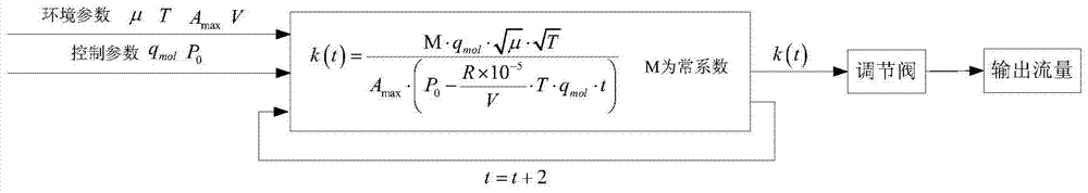
[0023] Write the PLC control program in advance according to the relationship between the pressure drop rate of the gas storage tank and the gas flow rate, and set the input parameters. During the pressure drop of the gas storage tank, the opening of the regulating valve is controlled by the PLC to increase continuously, and a gas storage tank is constructed. The feedforward control method of constant flow output is used for the constant flow supply of large flow gas in gas-liquid mixed reaction. The scheme includes PLC controller, pressure sensor, regulating valve, gas storage tank and pipeline, and stop valve.

[0024] The operation station is used for parameter setting and real-time monitoring. The PLC controller is used to calculate the valve opening and drive the regulating valve. The gas storage tank has stored a certain number of moles o...


PUM


Abstract

The present invention relates to a gas constant-flow output feedforward control system, which comprises a gas storage tank, an operation station, a PLC controller, a regulating valve, a stop valve and a pressure sensor, wherein the pressure sensor is arranged inside the gas storage tank, the output pipeline of the gas storage tank is sequentially provided with the regulating valve and the stop valve, and the PLC controller is connected with the operation station, the gas storage tank and the regulating valve. The method comprises that: the PLC controller detects the initial tank pressure and the temperature of the gas storage tank, and controls the regulating valve according to the control information transmitted by the operation station, and the PLC controller controls the stop valve to close when the gas output is not required. According to the present invention, the structure is simple, the control method is relatively simple and easy to perform, and the gas with the constant mol / s-grade flow can be output.

Description

technical field [0001] The invention relates to a feed-forward control system and method for constant gas flow output, in particular to a system and method for open-loop control of constant output of gas flow in a pipeline according to the differential form of the Clapeyron equation and the gas flow equation in the pipeline. Background technique [0002] At present, in order to make the gas in the pipeline output at a constant flow rate, there are several ways in the project: (1) install a steady flow device (such as a Venturi tube) in the pipeline; (2) install a pressure stabilizing valve in the pipeline; (3) ) to design the control algorithm by itself. Among them, the first method requires that the upstream pressure of the device is sufficiently large and constant, but in fact, the saturated vapor pressure of some gases determines that the gaseous pressure cannot be increased infinitely, and, unless the gas storage tank is large enough, as the gas Outflow, the upstream pr...

Claims


Application Information

Patent Timeline
Patent Type & Authority Applications(China)
IPC IPC(8): F17C7/00F17C13/02F17C13/04F17D3/01
Inventor 孙杨高虹廖伟光金玉奇
Owner DALIAN INST OF CHEM PHYSICS CHINESE ACAD OF SCI
Why Eureka
Try Eureka