
Battery packing module and battery pack

a battery pack and battery technology, applied in the field of battery pack module and battery pack, can solve the problems of increasing manufacturing cost, increasing process, and unable to mount the battery pack in a micro-mobility electric vehicle, and achieve the effect of facilitating the expansion of the battery pack, maintaining the output of the battery at a constant level, and minimizing the volume and weight of the whole battery pack

Active Publication Date: 2017-05-04
KOREA INST OF ENERGY RES
View PDF3 Cites 12 Cited by
  • Summary
  • Abstract
  • Description
  • Claims
  • Application Information

AI Technical Summary

Benefits of technology

The present invention provides a battery packing technology that allows for easy expansion based on battery capacity requirements and minimizes overall battery size and weight. Additionally, the battery pack is integrally provided with a structure for cooling heat generated from battery cells during use, which helps to maintain a constant battery output and extend its lifespan.

Problems solved by technology

However, since the battery pack in the related art has a structure in which the plurality of battery cells are simply packaged in the housing, there is a problem in that the battery pack has to be separately manufactured according to a required battery capacity, the process increases, and the manufacturing cost increases.
Further, in the related art, the size and volume of the battery pack are increased than necessary even when battery cells are connected in order to increase the battery capacity, so it may be impossible to mount the battery pack in a micro mobility electric vehicle.

Method used


Image

  • Battery packing module and battery pack
  • Battery packing module and battery pack
  • Battery packing module and battery pack

Examples


Embodiment Construction

[0037]Hereinafter, embodiments of the present invention will be described in detail with reference to the accompanying drawings. In adding reference numerals to elements in each drawing, the same elements will be designated by the same reference numerals, if possible, although they are shown in different drawings. Further, in the following description of the present invention, a detailed description of known functions and configurations incorporated herein will be omitted when it is determined that the description may make the subject matter of the present invention rather unclear.

[0038]In addition, terms, such as first, second, A, B, (a), (b) or the like may be used herein when describing components of the present invention. These terms are merely used to distinguish one structural element from other structural elements, and a property, an order, a sequence and the like of a corresponding structural element are not limited by the term. It should be noted that if it is described in ...


PUM


Abstract

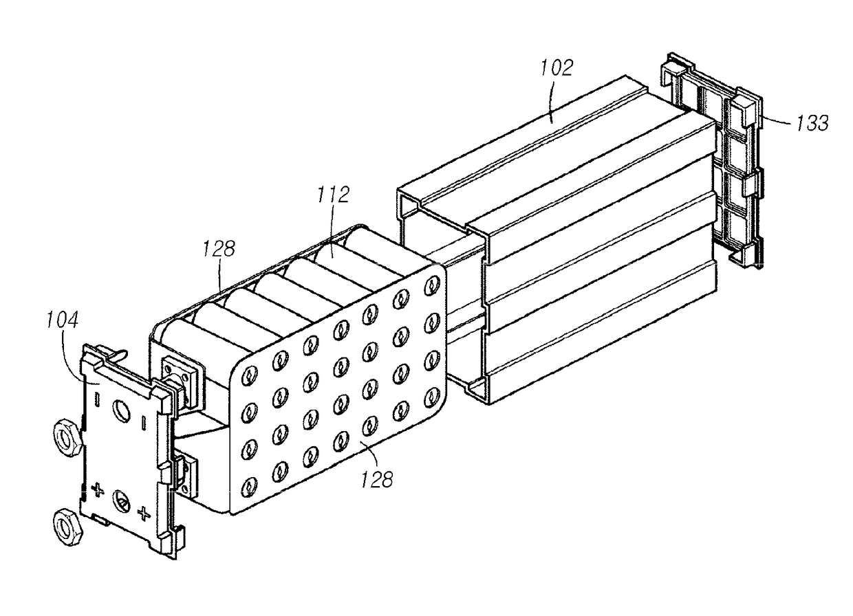
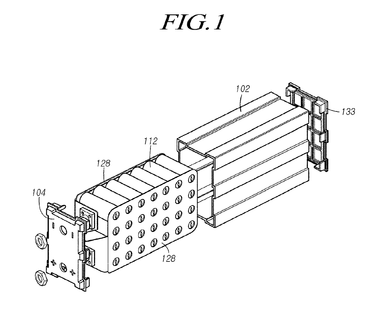
The present invention provides a battery packing module that includes: a heat dissipation member having a plurality of insertion cylinders arranged in a lattice type and a through-hole formed between the insertion cylinders in a direction that is parallel to the longitudinal direction of the insertion cylinders, wherein the outer circumferential surfaces of adjacent insertion cylinders are connected to each other; a plurality of cylindrical battery cells inserted into the insertion cylinders and configured to make contact with the inner circumferential surfaces of the insertion cylinders; and packing plates coupled to the upper ends and lower ends of the battery cells, wherein the packing plates have a current flow hole formed therein through which electrodes of the battery cells are exposed and battery mounting recesses formed therein in which the battery cells are mounted.

Description

CROSS-REFERENCE TO RELATED APPLICATIONS[0001]This application claims priority from Korean Patent Application No. 10-2015-0153043, filed on Nov. 2, 2015 and 10-2016-0090256 filed on Jul. 15, 2015 which are hereby incorporated by reference for all purposes as if fully set forth herein.BACKGROUND[0002]1. Field of the Invention[0003]The present invention relates to a battery packing module and a battery pack.[0004]2. Description of the Prior Art[0005]In recent years, various types of means of transportation using electricity, which is clean energy, have been developed through the convergence and innovation of high technologies. In particular, micro mobility electric vehicle technology has been actively developed on account of a limitation in parking spaces, traffic congestion, and the like, which are caused by the concentration of the population of cities.[0006]The spread of micro mobility electric vehicles is expected to be consistently increased due to the convenience and efficiency a...

Claims


Application Information

Patent Timeline
IPC IPC(8): H01M2/10H01M2/20H01M10/625H01M10/6569H01M10/6563H01M10/6551H01M10/643H01M50/213H01M50/224H01M50/503H01M50/516H01M50/522
CPCH01M2/1077H01M10/6551H01M2/206H01M2220/20H01M10/6569H01M10/6563H01M10/625H01M10/643H01M10/6557H01M10/655Y02E60/10H01M50/522H01M50/224H01M50/213H01M50/516H01M50/503
Inventor KIM, GANG CHULPYO, YOUNG DUGCHO, CHONG PYOWOO, YOUNG MINJANG, JIN YOUNGJUNG, YONG JINKIM, HAE KWANGKWON, OH SEUKJIN, CHANG SOO
Owner KOREA INST OF ENERGY RES
Learn More