
Vehicle and Control Method of the Same

a control method and vehicle technology, applied in hybrid vehicles, electrical control, instruments, etc., can solve the problems of increasing the overall size of the vehicle, increasing the total manufacturing cost, and poor acceleration feel, so as to reduce the torque command, the effect of constant and poor acceleration

Active Publication Date: 2008-02-21
TOYOTA JIDOSHA KK
View PDF9 Cites 15 Cited by
  • Summary
  • Abstract
  • Description
  • Claims
  • Application Information

AI Technical Summary

Benefits of technology

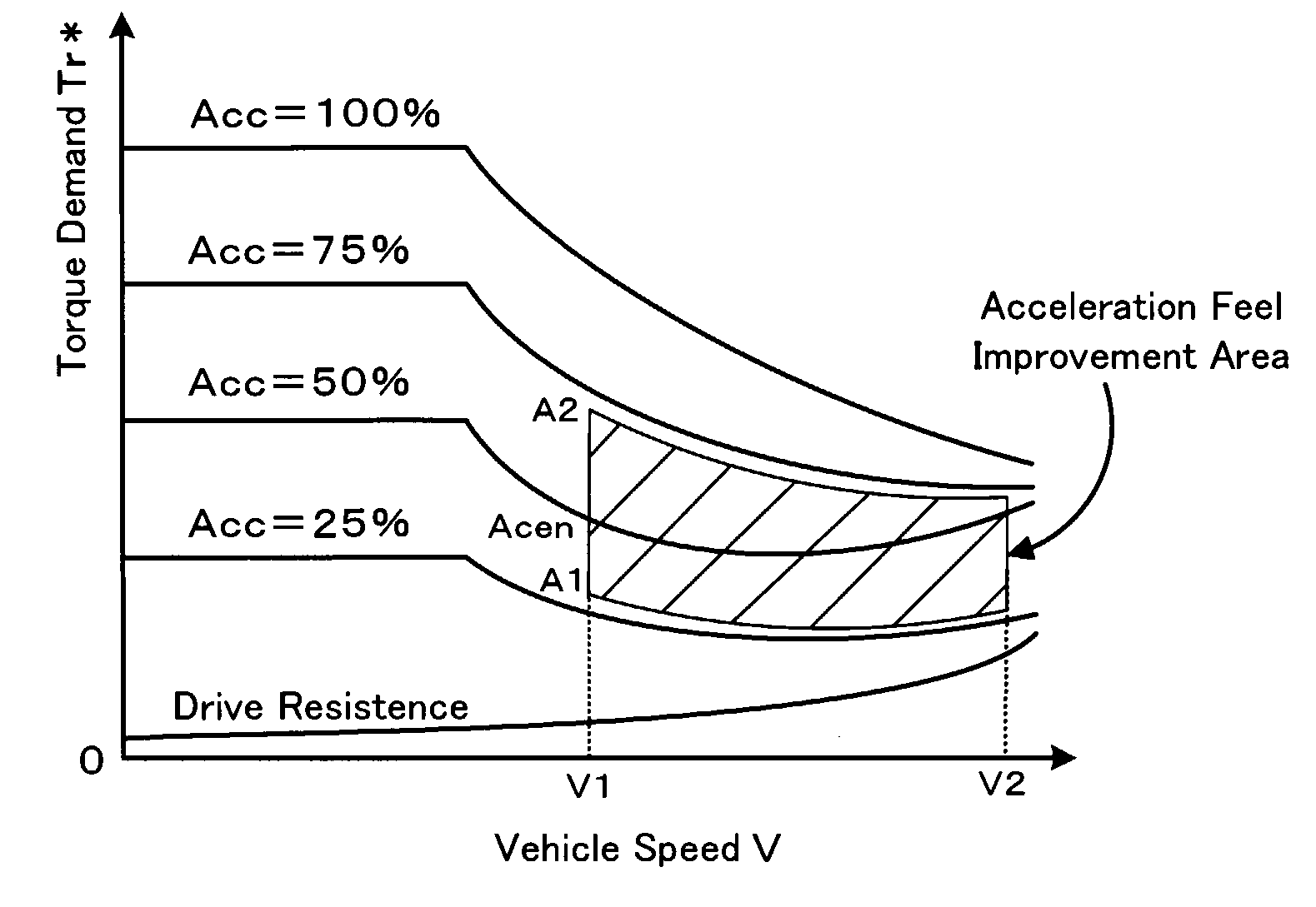
[0003] In the prior art vehicle discussed above, the torque command setting map is designed to decrease the torque command with an increase in rotation speed of the drive shaft, in order to ensure the substantially constant power level output to the drive shaft against the driver's depression amount of the accelerator pedal. Namely the acceleration of the vehicle decreases with an increase in vehicle speed under the condition of a fixed depression amount of the accelerator pedal to accelerate the vehicle. When the variation in torque command against the rotation speed of the drive shaft is determined to ensure output of the substantially constant power against the fixed depression amount of the accelerator pedal, the engine is generally driven at the drive point of the highest efficiency to ensure the required output power. The vehicle is accordingly accelerated at the substantially constant engine drive point (substantially uniform engine sound) under the condition of the fixed depression amount of the accelerator pedal. This state may lead to the poor acceleration feel. One possible measure to improve the driver's acceleration feel uses a high-performance engine and high-performance motors. The use of the power source having excess performances, however, undesirably expands the overall size of the vehicle and raises the total manufacturing cost.
[0009] In the vehicle of the invention, said second driving power demand setting module may set the lower driving power demand at the second reduction rate, which decreases against the measured accelerator depression amount closer to a specific depression level in the preset accelerator depression range.
[0011] In the vehicle of the invention, the second driving power demand setting module may set the driving power demand to accelerate the vehicle at a substantially constant acceleration against the measured accelerator depression amount regardless of the measured vehicle speed in a preset vehicle speed range, at least when the measured accelerator depression amount is substantially equal to a specific depression level in the preset accelerator depression range. This arrangement enables the vehicle to be accelerated at the substantially constant acceleration, at least when the accelerator depression amount is practically equal to the specific depression level.

Problems solved by technology

This state may lead to the poor acceleration feel.
The use of the power source having excess performances, however, undesirably expands the overall size of the vehicle and raises the total manufacturing cost.

Method used


Image

  • Vehicle and Control Method of the Same
  • Vehicle and Control Method of the Same
  • Vehicle and Control Method of the Same

Examples


first embodiment

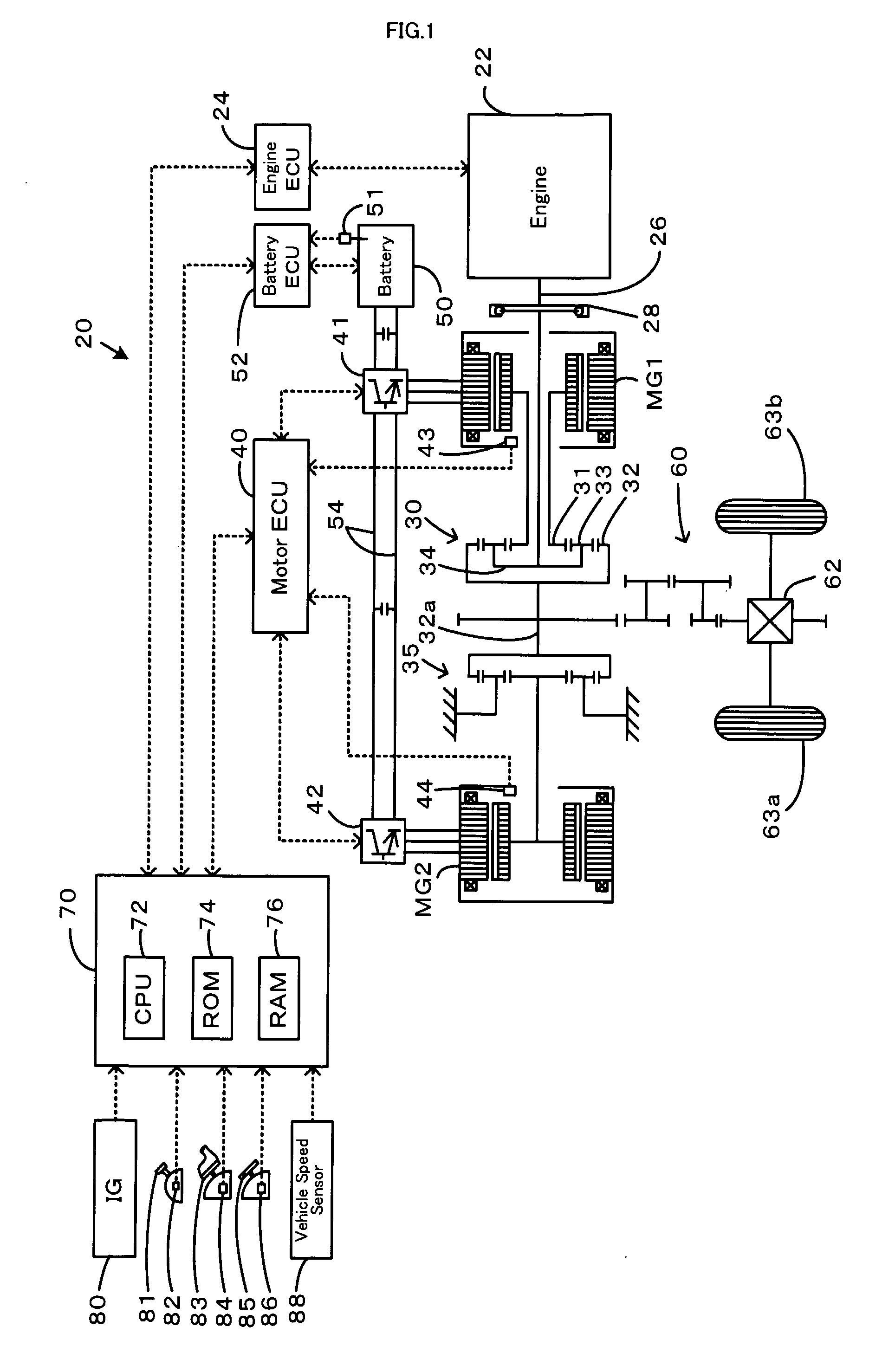
[0031] One mode of carrying out the invention is discussed below as a preferred embodiment. FIG. 1 schematically illustrates the construction of a hybrid vehicle 20 with a power output apparatus mounted thereon in one embodiment of the invention. As illustrated, the hybrid vehicle 20 of the first embodiment includes an engine 22, a three shaft-type power distribution integration mechanism 30 that is linked with a crankshaft 26 functioning as an output shaft of the engine 22 via a damper 28, a motor MG1 that is linked with the power distribution integration mechanism 30 and is capable of generating electric power, a reduction gear 35 that is attached to a ring gear shaft 32a functioning as a drive shaft connected with the power distribution integration mechanism 30, another motor MG2 that is linked with the reduction gear 35, and a hybrid electronic control unit 70 that controls the whole power output apparatus.

[0032] The engine 22 is an internal combustion engine that uses a hydroc...

second embodiment

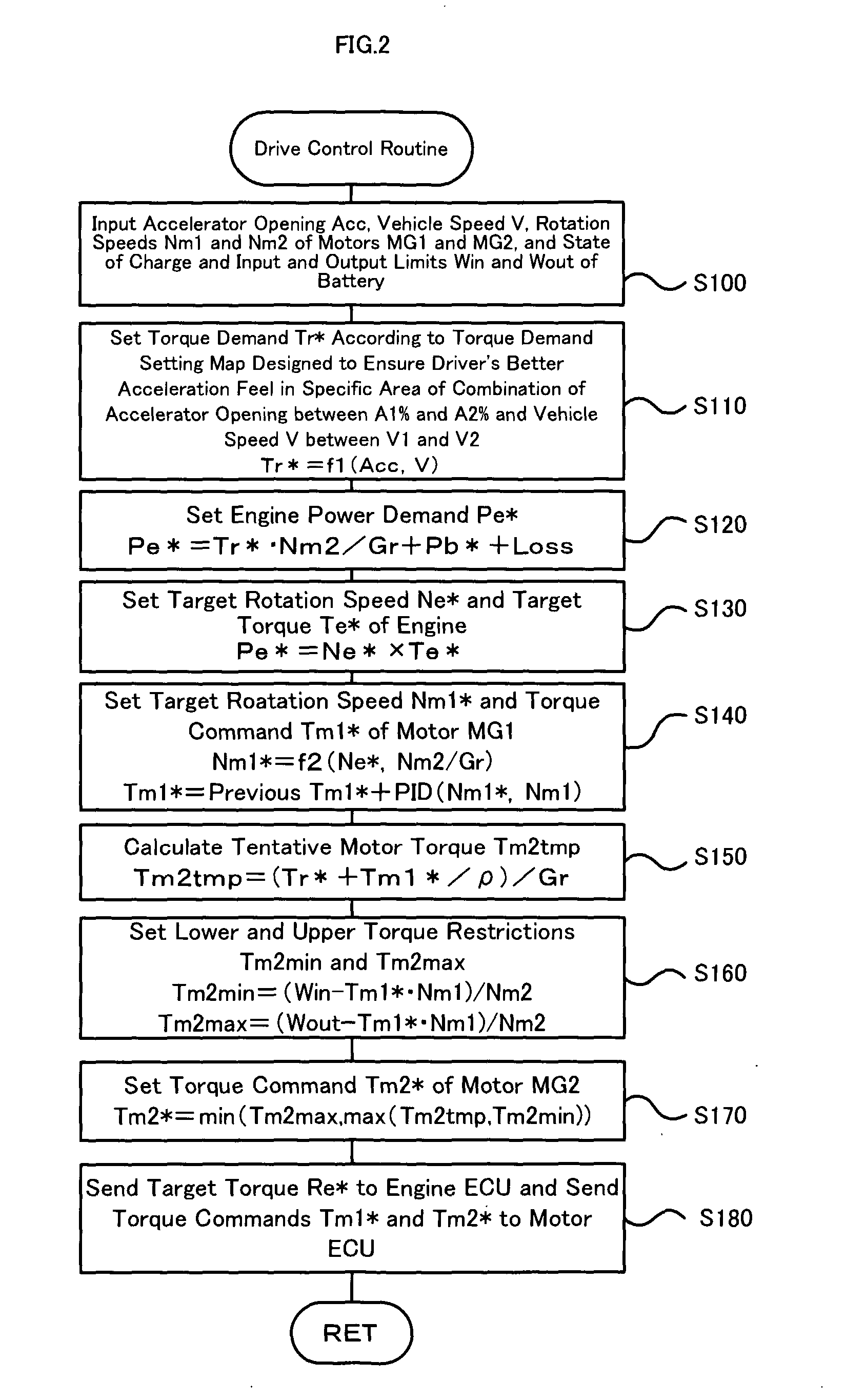
[0049] A hybrid vehicle 20B is described below as a second embodiment of the invention. The hybrid vehicle 20B of the second embodiment has the identical hardware configuration with that of the hybrid vehicle 20 of the first embodiment. The constituents and elements of the hybrid vehicle 20B of the second embodiment identical with those of the hybrid vehicle 20 of the first embodiment are thus expressed by the like numerals and symbols and are not specifically described here. FIG. 7 is a flowchart showing a drive control routine executed by the hybrid electronic control unit 70 included in the hybrid vehicle 20B of the second embodiment. This drive control routine is carried out repeatedly at preset time intervals (for example, at every 8 msec).

[0050] In the drive control routine, the CPU 72 of the hybrid electronic control unit 70 first inputs various data required for control, that is, the accelerator opening Acc, the vehicle speed V, the rotation speeds Nm1 and Nm2 of the motors...


PUM


Abstract

In a vehicle of the invention, a sun gear, a carrier, and a ring gear of a planetary gear mechanism are respectively connected to a first motor, to an engine, and to a drive shaft and a second motor. When the combination of measured accelerator opening and measured vehicle speed is in an ordinary acceleration area, the vehicle of the invention sets a torque demand to decrease with an increase in measured vehicle speed at a specific reduction rate that ensures the substantially constant output power to the drive shaft corresponding to the accelerator opening. When the combination of the measured accelerator opening and the measured vehicle speed is in an acceleration feel improvement area, on the other hand, the vehicle of the invention sets the torque demand to an extent of or below a maximum allowable value of the torque demand to decrease with an increase in measured vehicle speed at a lower reduction rate than the specific reduction rate. The lower reduction rate decreases against the accelerator opening closer to a center opening. The torque demand in the acceleration feel improvement area is also set to increase with an increase in measured vehicle speed with regard to the accelerator opening practically equal to the center opening. The vehicle controls the engine and the first and the second motors to ensure output of a torque equivalent to the torque demand to the drive shaft.

Description

TECHNICAL FIELD [0001] The present invention relates to a vehicle driven with power from a power output apparatus and a control method of such a vehicle. BACKGROUND ART [0002] In one proposed vehicle, a sun gear, a carrier, and a ring gear of a planetary gear mechanism are respectively connected to a first motor, to an engine, and to a second motor and a drive shaft linked with drive wheels (see, for example, Japanese Patent Laid-Open Gazette No. H09-308012). The proposed vehicle sets a torque command required to output to the drive shaft according to a torque command setting map, which decreases the torque command with an increase in rotation speed of the drive shaft (vehicle speed), in order to ensure a substantially constant power level output to the drive shaft against the driver's depression amount of an accelerator pedal. The output power of the engine goes through torque conversion by the planetary gear mechanism and the first and the second motors. Such torque conversion ena...

Claims


Application Information

Patent Timeline
Patent Type & Authority Applications(United States)
IPC IPC(8): B60K26/00B60W10/00F02D35/00B60L15/20B60L50/16F02D29/02F02D45/00
CPCB60K6/365Y10T477/623B60K6/445B60K6/48B60K6/52B60K26/00B60K2006/262B60W10/06B60W10/08B60W20/00B60W30/1882B60W2530/16B60W2540/10B60W2720/106F02D11/105Y02T10/6221Y02T10/623Y02T10/6265Y02T10/6286Y02T10/7258Y02T10/6239B60K6/44B60L15/20B60L2220/42B60L2220/52B60L2240/12B60L2240/16B60L2240/421B60L2240/423B60L2240/441B60L2240/443B60L2250/28B60L2270/145B60L50/16Y02T10/62Y02T10/64Y02T10/7072Y02T10/72B60W20/10Y02T10/70
Inventor KAYA, YASUHIRO
Owner TOYOTA JIDOSHA KK
Learn More