
Wave-shaped three-dimensional steel mesh welding device

A three-dimensional, welding device technology, applied in auxiliary devices, welding equipment, welding equipment, etc., can solve the problems of high cost, welding processing, complicated wall construction, etc., and achieve simple and convenient maintenance, high degree of automation, and high work efficiency. Effect

Inactive Publication Date: 2015-06-17
YUNNAN DEZHENG BUILDING NEW MATERIAL TECH
View PDF5 Cites 4 Cited by
  • Summary
  • Abstract
  • Description
  • Claims
  • Application Information

AI Technical Summary

Problems solved by technology

[0002] Most of the traditional partition walls used in buildings are steel-concrete structures. The construction of this kind of wall is complicated and the cost is high. At present, steel wire mesh frame light wall panels are also used as partition walls in building construction. The wall panels are all steel wire mesh frames. The structure of the solid wallboard compounded with lightweight filler and the wire mesh frame seems simple, but in order to meet the strength and corresponding mechanical requirements, the steel wire mesh frame has strict requirements on the welding process
The current welding equipment is especially not suitable for welding processing of three-dimensional steel mesh

Method used


Image

  • Wave-shaped three-dimensional steel mesh welding device
  • Wave-shaped three-dimensional steel mesh welding device

Examples


Embodiment Construction

[0013] The technical solution of this patent will be further described in detail below in conjunction with specific embodiments.

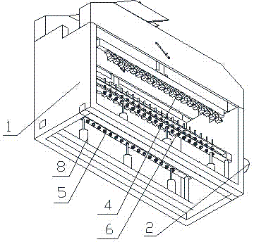
[0014] see figure 1 , a wave-shaped three-dimensional steel mesh welding device, including a frame 1, a horizontal wire automatic straightening wire feeding cutting machine 2, an upper wire square electrode 3, an upper wire straight electrode 4, a lower wire square electrode 5, and a lower wire straight electrode 6 , the upper electrode stroke control mechanism 7 and the lower electrode stroke control mechanism 8, the horizontal wire automatic straightening wire feeding and cutting machine 2 is installed on the right side of the frame 1, and the upper electrode stroke control mechanism 7 is installed on the top of the frame 1 , the lower electrode stroke control mechanism 8 is installed on the base plate of the frame 1, and the upper wire square electrode 3, the upper wire straight electrode 4, the lower wire square electrode 5 and the lower wire s...


PUM


Abstract

The invention discloses a wave-shaped three-dimensional steel mesh welding device. The wave-shaped three-dimensional steel mesh welding device comprises a rack, a horizontal wire automatic straightening wire feeding cut-off machine, upper wire square electrodes, upper wire straight electrodes, lower wire square electrodes, lower wire straight electrodes, an upper electrode stroke control mechanism and lower electrode stroke control mechanisms; the horizontal wire automatic straightening wire feeding cut-off machine is installed on the right side of the rack, the upper electrode stroke control mechanism is installed at the top of the rack, the lower electrode stroke control mechanisms are installed on the bottom plate of the rack, the lower wire square electrodes and the lower wire straight electrodes are installed above the lower electrode stroke control mechanisms, and the upper wire square electrodes and the upper wire straight electrodes are installed under the upper electrode stroke control mechanism. The positions of the upper wire square electrodes, the upper wire straight electrodes, the lower wire square electrodes and the lower wire straight electrodes are adjustable, products with different mesh specifications and different kinds can be produced, the device can be controlled by the upper electrode stroke control mechanism and the lower electrode stroke control mechanisms, the degree of automation is high, the failure rate is low, and the work efficiency is high.

Description

technical field [0001] The invention relates to a welding device, in particular to a wave-shaped three-dimensional steel mesh welding device. Background technique [0002] Most of the traditional partition walls used in buildings are steel-concrete structures. The construction of this kind of wall is complicated and the cost is high. At present, steel wire mesh frame light wall panels are also used as partition walls in building construction. The wall panels are all steel wire mesh frames. The structure of the solid wallboard compounded with lightweight filler and the steel wire mesh frame seems simple, but in order to meet the strength and corresponding mechanical requirements, the steel wire mesh frame has strict requirements on the welding process. The current welding equipment is especially not suitable for the welding process of three-dimensional steel mesh. Contents of the invention [0003] The object of the present invention is to provide a wave-shaped three-dimen...

Claims


Application Information

Patent Timeline
IPC IPC(8): B23K31/02B23K37/00
CPCB21F27/10B21F1/026B23K11/00B23K11/31
Inventor 刘德政
Owner YUNNAN DEZHENG BUILDING NEW MATERIAL TECH
Learn More