High spatial resolution laser confocal mass spectrometry microscopy imaging method and device

A high spatial resolution, microscopic imaging technology, applied in the field of confocal microscopic imaging technology and mass spectrometry imaging, can solve the problems of low spatial resolution of mass spectrometry detection, large laser focusing spot, drift, etc., so as to improve the spatial resolution ability and suppress drift. Effect

Active Publication Date: 2018-07-20
BEIJING INSTITUTE OF TECHNOLOGYGY
View PDF6 Cites 0 Cited by
  • Summary
  • Abstract
  • Description
  • Claims
  • Application Information

AI Technical Summary

Problems solved by technology

[0005] 1) Due to the use of simple laser focusing to desorb and ionize the sample, there are still problems such as large laser focusing spot and low spatial resolution of mass spectrometry detection;
[0006] 2) The time required for mass spectrometry imaging is long, and the axial position of the focused spot of the laser mass spectrometer often drifts relative to the sample to be measured

Method used


Image

  • High spatial resolution laser confocal mass spectrometry microscopy imaging method and device
  • High spatial resolution laser confocal mass spectrometry microscopy imaging method and device
  • High spatial resolution laser confocal mass spectrometry microscopy imaging method and device

Examples


Embodiment 1

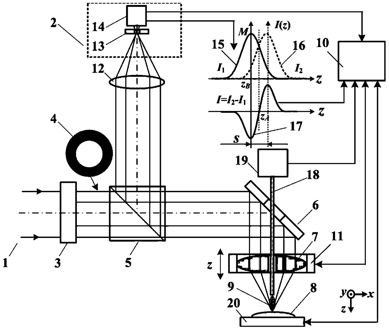
[0047] The embodiment of the present invention is based on Figure 4 The shown high spatial resolution laser confocal mass spectrometry imaging device includes a laser point light source system 24 composed of a pulsed laser 26, a focusing lens 27 and a pinhole 28 located at the focus of the focusing lens 27, and a collimator placed along the optical axis direction Lens 25, exit beam attenuator 29, ring light generating system 3, spectroscope 5, center hole mirror 6 and center hole measurement objective lens located in the refraction direction of the optical axis and focusing the light beam reflected by the center hole mirror 6 to the measured sample 8 7. It also includes a confocal light intensity detection system composed of a detection beam attenuator 30, a collecting lens 12, a light intensity point detector 2 located at the focal point of the laser lens 12, and a device for detecting the focused light spot of the middle hole measurement objective lens 7 and analyzing the io...

Embodiment 2

[0065] Such as Figure 4 As shown, in the high-spatial-resolution laser confocal mass spectrometer imaging device of Embodiment 1, the computer 10 can use the position z corresponding to the maximum value M of the confocal axial intensity curve 15 B The value is used to control the axial objective lens scanner 11 so that the focusing spot of the middle hole measurement objective lens 7 is focused on the measured sample 8 .

[0066] The remaining imaging measurement methods are the same as in Example 1.

Embodiment 3

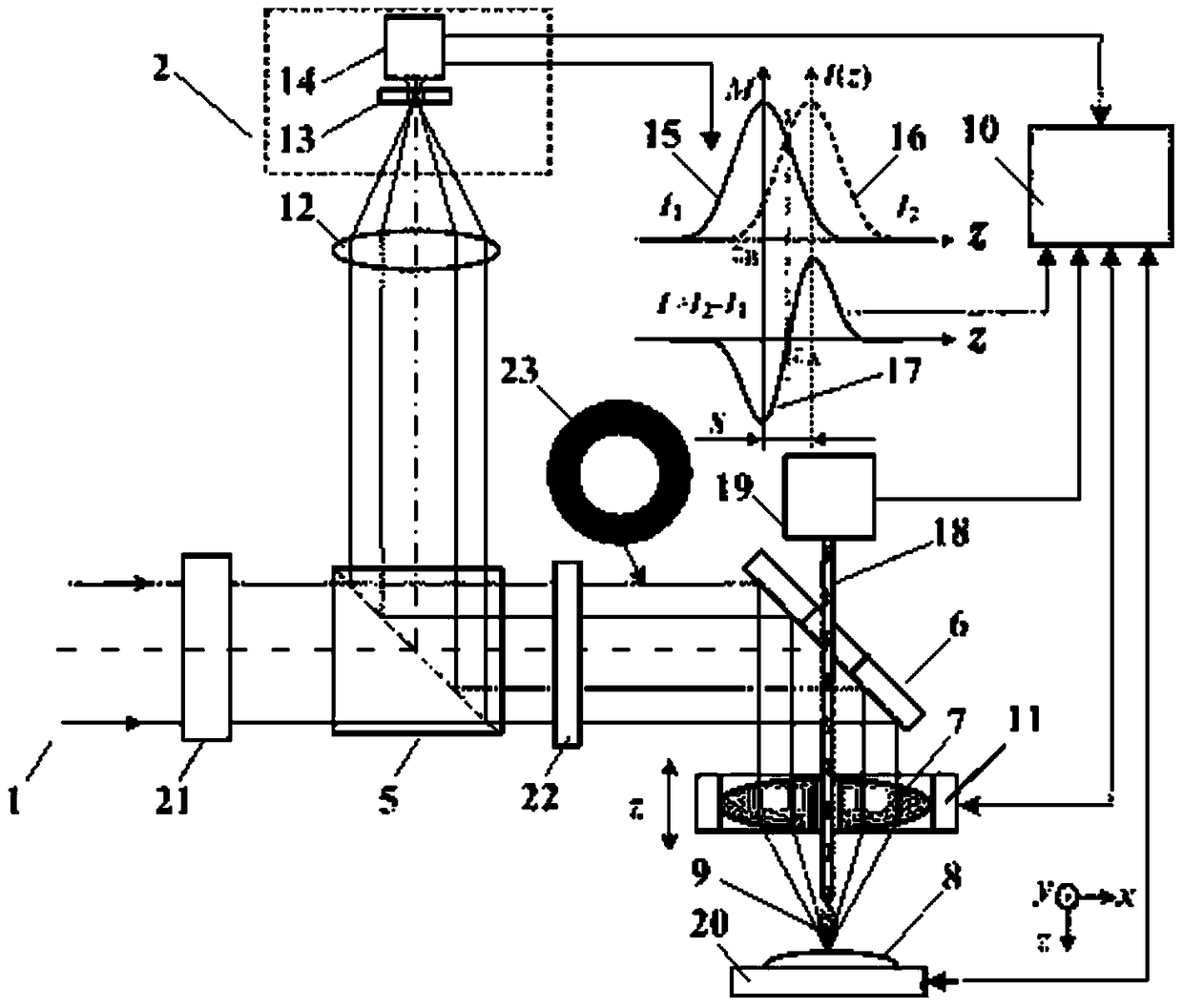
[0068] Such as Figure 5 As shown, in the high spatial resolution laser confocal mass spectrometer imaging device of embodiment 1, the ring light generating system 3 is replaced by a vector beam generating system 21 and a pupil filter 22 placed along the optical axis direction to generate a vector beam, generating The annular light beam 23 is focused to a tiny light spot exceeding the diffraction limit after passing through the center-hole reflector 6 and the center-hole measuring objective lens 7 and irradiates the measured sample 8 .

[0069] The radially polarized light longitudinal field tight focusing system composed of the vector beam generating system 21 , the pupil filter 22 and the center hole measurement objective lens 7 is used to compress the lateral size of the focused spot.

[0070] The remaining imaging measurement methods are the same as in Example 1.


PUM


Abstract

The invention relates to a high-spatial resolution laser confocal mass spectrometry microimaging method and device, and belongs to the technical fields of confocal microimaging and mass spectrometry imaging. According to the method, the confocal imaging technology, the mass spectrometry imaging technology and the spectral detection technology are combined, axial focus fixing and imaging are performed on a sample by use of the focusing spot of a high-spatial resolution confocal microscopic system, and the same focusing spot of the high-spatial resolution differential confocal microscopic system is used for desorption ionization of the sample to realize mass spectrometry imaging, and consequently, high-spatial resolution imaging of the micro-area images and the components of the sample is realized. The device comprises a point light source, a collimating lens, a ring light generation system, a light splitter, a mesoporous reflector and a mesoporous measuring objective, as well as a light collecting lens for detecting the reflected light intensity signal of the focusing spot of the mesoporous reflector, a light intensity point detector located at the focal point of the light collecting lens, an ionization sample suction pipe for detecting plasma plume components obtained by virtue of desorption ionization with the focusing spot of the mesoporous measuring objective and a mass spectrometry detection system. The method and the device are applicable to high resolution imaging of the biomass spectrometry.

Description

technical field [0001] The invention belongs to the field of confocal microscopic imaging technology and mass spectrometry imaging technology, combines laser confocal microscopic imaging technology and mass spectrometry imaging technology, and relates to a high spatial resolution laser confocal mass spectrometry microscopic imaging method and device, which can be used in the field of biological mass spectrometry imaging High resolution imaging. technical background [0002] Mass Spectrometry (Mass Spectrometry) is to ionize the components in the sample, so that the generated charged atoms, molecules or molecular fragments with different charge-to-mass ratios are respectively focused under the action of an electric field and a magnetic field to obtain a sequence of mass-to-charge ratios. Spectrograph instrument. Mass spectrometry imaging is to perform mass spectrometry analysis on multiple small areas in the two-dimensional area of ​​the sample to detect the distribution of ...

Claims


Application Information

Patent Timeline
Patent Type & Authority Patents(China)
IPC IPC(8): G01N27/64G01N21/00
Inventor 赵维谦邱丽荣
Owner BEIJING INSTITUTE OF TECHNOLOGYGY
Why Eureka
Try Eureka