High spatial resolution laser split pupil confocal mass spectrometry imaging method and device

A high spatial resolution microscopic imaging technology, applied in the field of confocal microscopic imaging technology and mass spectrometry imaging, can solve the problems of low spatial resolution of mass spectrometry detection, large laser focus spot, long time of mass spectrometry imaging, etc., to improve the spatial resolution capability , Strong anti-stray light ability, and the effect of overcoming the interference of stray light on the focal plane

Active Publication Date: 2017-03-29
BEIJING INSTITUTE OF TECHNOLOGYGY
View PDF7 Cites 0 Cited by
  • Summary
  • Abstract
  • Description
  • Claims
  • Application Information

AI Technical Summary

Problems solved by technology

[0006] 1) Due to the use of simple laser focusing to desorb and ionize the sample, there are still problems such as large laser focusing spot and low spatial resolution of mass spectrometry detection;
[0007] 2) The time required for mass spectrometry imaging is long, and the axial position of the focused spot of the laser mass spectrometer often drifts relative to the sample to be measured

Method used


Image

  • High spatial resolution laser split pupil confocal mass spectrometry imaging method and device
  • High spatial resolution laser split pupil confocal mass spectrometry imaging method and device
  • High spatial resolution laser split pupil confocal mass spectrometry imaging method and device

Examples


Embodiment 1

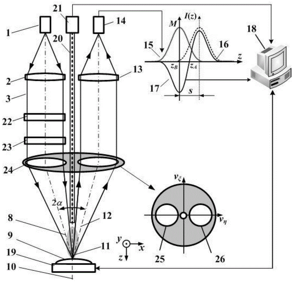
[0045] Such as figure 2 In the shown high spatial resolution laser split pupil confocal mass spectrometry imaging device, the compressed focusing spot system 4 is replaced by a vector beam generating system 22 and a pupil filter 23 . The D-shaped illumination collector mirror 5 can be replaced by a circular illumination collector mirror 24 .

[0046] Such as figure 2 The shown high spatial resolution laser pupil confocal mass spectrometry imaging device includes a point light source 1, a collimator lens 2 placed along the direction of the incident optical axis 8, a vector beam generation system 22, a pupil filter 23 and a focusing spot to be The circular illumination pupil 25 of the circular illumination collection mirror 24 of the test sample 9 also includes the circular collection pupil 26 of the circular illumination collection mirror 24, the collection lens 13 located in the direction of the collection optical axis 12 and the focal point of the collection lens 13. The ...

Embodiment 2

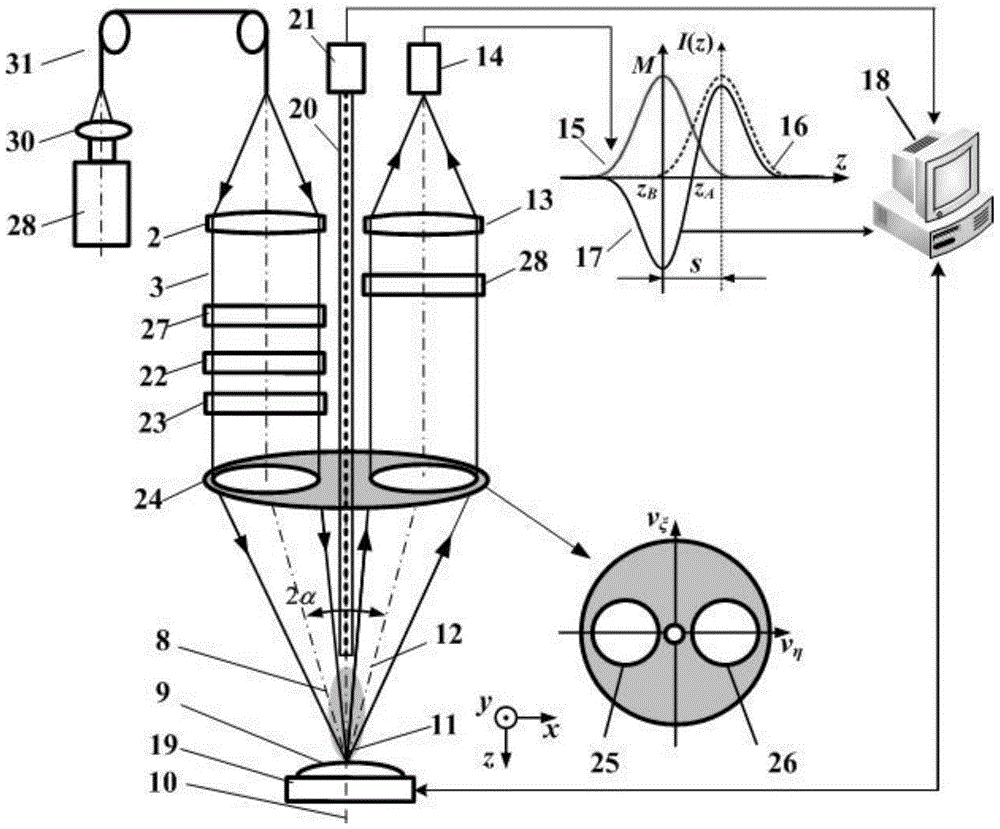
[0064] Such as image 3 In the shown high spatial resolution laser split pupil confocal mass spectrometry imaging device, the point light source 1 is replaced by a pulsed laser 29 along the direction of the incident optical axis 8, a condenser lens 30, and a light-transmitting optical fiber 31 at the focal point of the condenser lens 30 , the compressed focusing spot system 4 is replaced by a vector beam generation system 22 and a pupil filter 23 . The D-shaped illuminating collector mirror 5 is replaced by a circular illuminating collecting mirror 24 . At the same time, an exit beam attenuator 27 is introduced into the laser focusing system, and a detection beam attenuator 28 is introduced into the laser split pupil confocal detection system.

[0065] The radially polarized light longitudinal field tight focusing system composed of the vector beam generating system 22 , the pupil filter 23 and the circular illumination pupil 25 of the circular illumination collecting mirror ...


PUM


Abstract

The invention relates to a high-spatial resolution laser splitting-pupil confocal mass spectrometry microimaging method and device, and belongs to the technical fields of confocal microimaging and mass spectrometry imaging. According to the method, the splitting-pupil confocal imaging technology and the mass spectrometry and spectrum detection technologies are combined, high-spatial resolution morphological imaging is performed on a sample by use of the focusing micro-spot, treated by use of a super-resolution technology, of a splitting-pupil confocal microscope, a mass spectrometry detection system is used for performing micro-area mass spectrometry imaging on charged molecules, atoms and the like generated by performing desorption ionization on the sample with the focusing spot of a splitting-pupil confocal microscopic system, and then complete sample component information can be obtained by virtue of the fusion and the comparison of the detection data information; as a result, micro-area high-spatial resolution and high-sensitivity imaging and detection on the morphology and the components of the sample to be tested are realized. The method and device are used for overcoming the defect that the existing confocal microimaging technology is incapable of inhibiting the interference of the focal plane stray light, and are high in stray light resisting capability; a brand new effective technical way is provided for high resolution imaging of the biomass spectrometry.

Description

technical field [0001] The invention belongs to the field of confocal microscopic imaging technology and mass spectrometry imaging technology, combines split-pupil confocal microscopic imaging technology and mass spectrometry imaging technology, and relates to a high spatial resolution laser split-pupil confocal mass spectrometry microscopic imaging method and device, which can be used for biological mass spectrometry high-resolution imaging. [0002] technical background [0003] Mass Spectrometry (Mass Spectrometry) is to ionize the components in the sample, so that the generated charged atoms, molecules or molecular fragments with different charge-to-mass ratios are respectively focused under the action of an electric field and a magnetic field to obtain a sequence of mass-to-charge ratios. Spectrograph instrument. Mass spectrometry imaging is to perform mass spectrometry analysis on multiple small areas in the two-dimensional area of ​​the sample to detect the distributi...

Claims


Application Information

Patent Timeline
Patent Type & Authority Patents(China)
IPC IPC(8): G01N21/71G01N27/64
Inventor 赵维谦王允
Owner BEIJING INSTITUTE OF TECHNOLOGYGY
Why Eureka
Try Eureka