Sputter deposition method, sputtering system, manufacture of photomask blank, and photomask blank

A technology of photomask blanks and sputtering deposition, which is applied in the direction of sputtering coating, originals for photomechanical treatment, photoplate making process of pattern surface, etc., can solve the problem of imposing degrees of freedom, limitation of degrees of freedom in film design, Restrictions and other issues

Inactive Publication Date: 2015-06-10
SHIN ETSU CHEM IND CO LTD
View PDF10 Cites 5 Cited by
  • Summary
  • Abstract
  • Description
  • Claims
  • Application Information

AI Technical Summary

Problems solved by technology

This imposes constraints on the degrees of freedom in membrane design
In addition, when a chromium-based compound having light elements added thereto is used as a hard mask film instead of a light-shielding film (the hard mask film is used for the processing of the light-shielding film), the range of usable light elements ensuring the necessary functions is limited. duely limit
The freedom of membrane design is also limited in this case

Method used


Image

  • Sputter deposition method, sputtering system, manufacture of photomask blank, and photomask blank
  • Sputter deposition method, sputtering system, manufacture of photomask blank, and photomask blank
  • Sputter deposition method, sputtering system, manufacture of photomask blank, and photomask blank

Examples


Embodiment 1 and 2

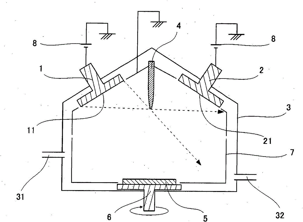
[0089] Equipped as figure 1 The shown DC magnetron sputtering system, Sn target as the first target, Cr target as the second target, Ar inert gas and N 2 and O 2 The reactive gas serves as the sputtering gas. A conductive plate 150 mm high by 500 mm wide was used as a barrier member between the targets and aligned with the perpendicular bisector of the line segment connecting the centers of the sputtering surfaces of the two targets. The barrier member is arranged in a region where it intersects all straight lines connecting any arbitrary point on the sputtering surface of the Sn target and any arbitrary point on the sputtering surface on the Cr target. The substrate used was a 6025 quartz substrate for a photomask, on which a CrSnON film was deposited.

[0090] Regarding the discharge, the power is constant, and the current and voltage values ​​for each target vary depending on the sputtering environment. The power of the Cr target was fixed at 1,000 W, and the power of t...


PUM

PropertyMeasurementUnit
melting pointaaaaaaaaaa

Abstract

A film is sputter deposited on a substrate by providing a vacuum chamber (3) with first and second targets (1, 2) such that the sputter surfaces (11, 21) of the first and second targets (1, 2) may face the substrate (5) and be arranged parallel or oblique to each other, simultaneously supplying electric powers to the first and second targets (1, 2), and depositing sputtered particles on the substrate while controlling sputtering conditions such that the rate at which sputtered particles ejected from one target reach the sputter surface of the other target and deposit thereon is not more than the rate at which the sputtered particles are removed from the other target by sputtering.

Description

technical field [0001] The present invention relates to a sputtering deposition method using the co-deposition technique of sputtering two or more targets at the same time, a sputtering system suitable for the sputtering deposition method, using the sputtering deposition method or the sputtering system to manufacture Method for photomask blanks of functional films deposited on transparent substrates, and photomask blanks manufactured using the sputter deposition method or sputtering system. Background technique [0002] In the field of semiconductor technology, research and development efforts continue to further reduce the size of pattern features. The challenge of higher integrated large-scale integrated circuits places increasing demands on the miniaturization of circuit patterns. There is an increasing demand for further reduction in size of wiring patterns constituting circuits and miniaturization of contact hole patterns for interlayer connections constituting trenche...

Claims


Application Information

Patent Timeline
Patent Type & Authority Applications(China)
IPC IPC(8): C23C14/54C23C14/34C23C14/14G03F1/68
CPCC23C14/3464C23C14/0676C23C14/352G03F1/68H01J37/3417H01J37/3441H01J37/3447
Inventor 笹本纮平深谷创一中川秀夫稻月判臣
Owner SHIN ETSU CHEM IND CO LTD
Why Eureka
Try Eureka