
Deep-space-communication-oriented cross-layer joint file transmission method and system

A technology of file transmission and deep space communication, which is applied in the field of deep space communication, can solve problems such as structural redundancy, complex implementation, and lack of thorough improvement in data transmission, and achieve the effects of good performance, improved throughput, and improved performance

Inactive Publication Date: 2015-06-03
HARBIN INST OF TECH SHENZHEN GRADUATE SCHOOL
View PDF2 Cites 6 Cited by
  • Summary
  • Abstract
  • Description
  • Claims
  • Application Information

AI Technical Summary

Problems solved by technology

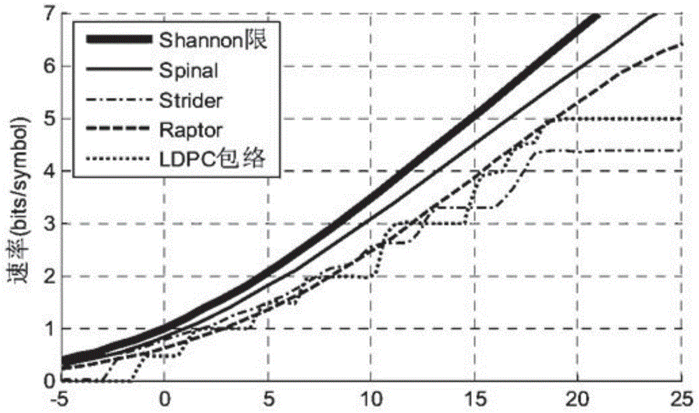
like image 3 As shown, the disadvantage is that due to the need for the cooperation of the lower layer error detection mechanism, the structure is redundant and the implementation is more complicated
Both of these two protocols have improved the communication constraints of deep space channels, but SCPS has not made corresponding changes with the increase of communication bandwidth, and there are serious security problems
The CFDP protocol has not completely improved the transmission mechanism of the TCP / IP protocol, such as data transmission and forwarding after the connection is established first. It is still based on the end-to-end retransmission mechanism, which cannot well deal with the difficulty of huge delay in deep space communication. , so in the deep space environment, the application of these two protocols also has certain limitations

Method used


Image

  • Deep-space-communication-oriented cross-layer joint file transmission method and system
  • Deep-space-communication-oriented cross-layer joint file transmission method and system
  • Deep-space-communication-oriented cross-layer joint file transmission method and system

Examples


Embodiment Construction

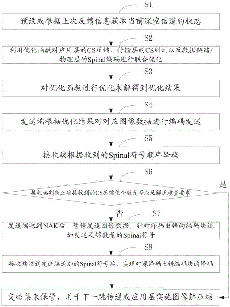
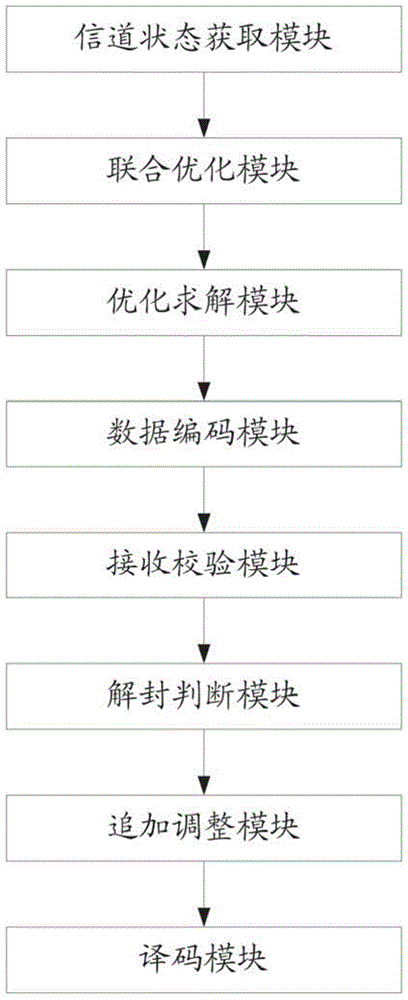
[0039] figure 1 It shows the flow chart of the cross-layer joint file transfer method for deep space communication provided by the present invention, which is described in detail as follows: The cross-layer joint file transfer method includes two models, namely the cross-layer joint optimization model and the cross-layer joint optimization model. Joint transfer model.

[0040] Step S1, preset or obtain the current state of the deep-space channel according to the last feedback information; optimize the basis for model establishment; according to the memory of the state of the deep-space channel, the deep-space channel can be modeled as a Markov process. The use of Markov prediction is to send subsequent data directly without waiting for feedback. According to the signal-to-noise ratio, the deep-space channel can be divided into multiple channel states, and the initial state and state transition probability matrix can be used for Markov prediction. To establish the CDF functi...


PUM


Abstract

The invention is applicable to the field of deep space communication, and provides a deep-space-communication-oriented cross-layer joint file transmission method. An image is compressed by adopting a CS (chirp scaling) algorithm in the transmission process of the image, so that the image can be jointly optimized with the Spinal code of a bottom layer and then is transmitted; a cross-layer joint transmission mechanism refers to that the CS image compression of an application layer, the CS erasure correction of a transmission layer and the Spinal code of a data link layer / physical layer are jointly optimized and a transmission mechanism is designed in combination with an LTP (Licklider transmission protocol), and after finishing sending certain data, a sending end determines a symbolic number to be sent at a next moment through Markov prediction and feedback information without waiting for feedback. After receiving the feedback, the sending end pauses sending the data, processes the feedback, and additionally sends the symbolic number aiming at a coding block with an error, and the additionally sent symbolic number is decoded together with the symbolic number sent before. On the premise that certain reliability is guaranteed, the effectiveness of a system is improved.

Description

technical field [0001] The invention belongs to the field of deep space communication, in particular to an image data transmission method. Background technique [0002] Deep space communication has the characteristics of long distance, long delay, and intermittent link, which makes the contradictory relationship between the reliability and effectiveness of deep space communication more prominent. For this problem, the traditional solutions include increasing the receiving / transmitting antenna size, increasing the carrier frequency, increasing the transmitting power, controlling the noise level of the receiving system, etc., but the method based on physical quantity gain is ultimately unsustainable. Efficient channel coding and reasonable transmission mechanism play an important role in deep space communication. [0003] In channel coding, existing high-performance coding techniques such as Turbo codes and LDPC codes perform well under medium SNR conditions, but are still un...

Claims


Application Information

Patent Timeline
IPC IPC(8): H04L1/00H04L1/16
Inventor 吴绍华生海洋陈大薇王野张钦宇
Owner HARBIN INST OF TECH SHENZHEN GRADUATE SCHOOL
Learn More