
A method of manufacturing a light-emitting diode

A technology of light-emitting diodes and manufacturing methods, which is applied in the direction of electrical components, circuits, semiconductor devices, etc., can solve the problems of light-emitting diode current congestion, low light extraction efficiency, and poor current distribution uniformity, and achieve the effect of reducing current congestion

Inactive Publication Date: 2018-02-16
EPILIGHT TECH
View PDF6 Cites 0 Cited by
  • Summary
  • Abstract
  • Description
  • Claims
  • Application Information

AI Technical Summary

Problems solved by technology

[0007] In view of the above-mentioned shortcomings of the prior art, the object of the present invention is to provide a method for manufacturing a light-emitting diode, which is used to solve the problems of current congestion, poor current distribution uniformity, and low light extraction efficiency of the light-emitting diode in the prior art.

Method used


Image

  • A method of manufacturing a light-emitting diode
  • A method of manufacturing a light-emitting diode
  • A method of manufacturing a light-emitting diode

Examples


Embodiment Construction

[0049]Embodiments of the present invention are described below through specific examples, and those skilled in the art can easily understand other advantages and effects of the present invention from the content disclosed in this specification. The present invention can also be implemented or applied through other different specific implementation modes, and various modifications or changes can be made to the details in this specification based on different viewpoints and applications without departing from the spirit of the present invention.

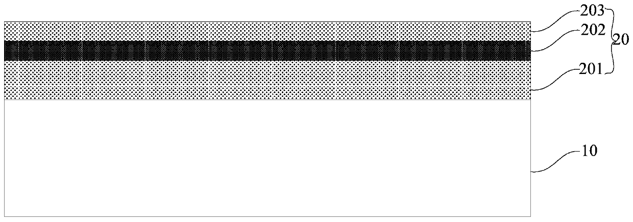
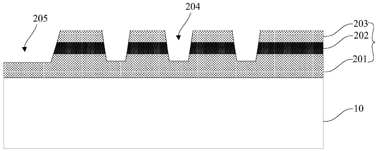
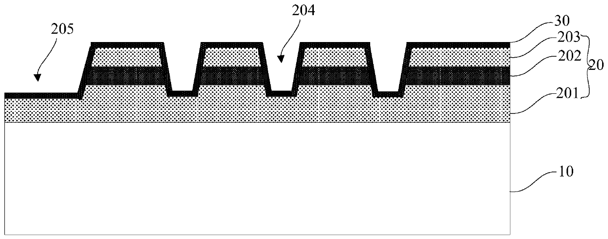
[0050] see Figure 1 to Figure 9 . It should be noted that the diagrams provided in this embodiment are only schematically illustrating the basic idea of ​​the present invention, and only the components related to the present invention are shown in the diagrams rather than the number, shape and shape of the components in actual implementation. Dimensional drawing, the type, quantity and proportion of each component can be changed arbi...


PUM


Abstract

The invention provides a method for manufacturing a light-emitting diode, comprising steps: 1) forming a light-emitting epitaxial structure on the surface of a growth substrate; 2) simultaneously etching an N-electrode platform and a plurality of holes in each light-emitting unit, and the plurality of holes Located between the N electrode platform and the P electrode; 3) Tangentially forming multiple cutting grooves; 4) Depositing a SiO2 layer and removing the SiO2 layer in each hole; 5) Using chemical etching to etch out multiple holes at the bottom of each hole dislocation pits, and remove the residues in each cutting groove at the same time; 6) form the SiO2 layer again; 7) remove part of the SiO2 layer, retain the bottom and side walls of each hole, and the SiO2 layer under the P electrode ; 8) forming a current spreading layer; 9) preparing a P electrode and an N electrode. The invention can reduce the current congestion of the light-emitting diode, improve the uniformity of current distribution, and improve the light-emitting efficiency of the light-emitting diode by making a plurality of holes between the P electrode and the N electrode and forming dislocation pits at the bottom of the holes.

Description

technical field [0001] The invention belongs to the field of semiconductor lighting, in particular to a method for manufacturing a light emitting diode. Background technique [0002] As a new type of high-efficiency solid light source, semiconductor lighting has significant advantages such as long life, energy saving, environmental protection, and safety. It will become another leap in the history of human lighting after incandescent lamps and fluorescent lamps. The upgrading of the industry and other industries has huge economic and social benefits. Because of this, semiconductor lighting is generally regarded as one of the most promising emerging industries in the 21st century, and also one of the most important commanding heights in the field of optoelectronics in the next few years. Light-emitting diodes LEDs are made of III-IV compounds, such as GaAs (gallium arsenide), GaP (gallium phosphide), GaAsP (gallium arsenide phosphide) and other semiconductors, and its core i...

Claims


Application Information

Patent Timeline
Patent Type & Authority Patents(China)
IPC IPC(8): H01L33/00
Inventor 朱广敏郝茂盛
Owner EPILIGHT TECH
Learn More