
LED chip and its preparation method

A technology of LED chips and epitaxial wafers, which is applied in the direction of semiconductor devices, electrical components, circuits, etc., can solve the problems of uneven local current diffusion, uneven current diffusion, and high current density, so as to improve luminous efficiency, reduce current congestion, The effect of prolonging life

Active Publication Date: 2018-09-11
BYD SEMICON CO LTD
View PDF4 Cites 0 Cited by
  • Summary
  • Abstract
  • Description
  • Claims
  • Application Information

AI Technical Summary

Problems solved by technology

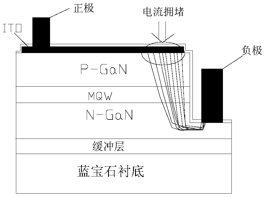
[0006] Although holes are made on the surface of the ITO layer to alleviate the uneven phenomenon of current preferentially diffusing to the negative electrode area, there are also some problems. For example, the local diffusion of current on the surface of the ITO layer is uneven, and the current will flow preferentially to the area without ITO holes. That is: the area without holes on the ITO has a large current density, while the area with holes has a small current density, which will also cause uneven current diffusion.

Method used


Image

  • LED chip and its preparation method
  • LED chip and its preparation method
  • LED chip and its preparation method

Examples


Embodiment Construction

[0028] Embodiments of the present invention are described in detail below, examples of which are shown in the drawings, wherein the same or similar reference numerals designate the same or similar elements or elements having the same or similar functions throughout. The embodiments described below by referring to the figures are exemplary only for explaining the present invention and should not be construed as limiting the present invention.

[0029] The following disclosure provides many different embodiments or examples for implementing different structures of the present invention. To simplify the disclosure of the present invention, components and arrangements of specific examples are described below. Of course, they are only examples and are not intended to limit the invention. Furthermore, the present invention may repeat reference numerals and / or letters in different instances. This repetition is for the purpose of simplicity and clarity and does not in itself indicat...


PUM


Abstract

The invention provides a LED chip. The LED chip comprises a substrate, a buffer layer, an N-type semiconductor layer, an illuminating layer, a P-type semiconductor layer, a transparent conductive layer, a P-type electrode and an N-type electrode, wherein the buffer layer, the N-type semiconductor layer, the illuminating layer, the P-type semiconductor layer and the transparent conductive layer are successively arranged on the substrate; the surface of the transparent conductive layer is provided with a plurality of concentric arc grooves with different intervals; the P-type electrode is electrically connected with the transparent conductive layer and is disposed on the transparent conductive layer; and the N-type electrode is electrically connected with the N-type semiconductor layer and is next to the transparent conductive layer. By using the LED chip, current congestion can be effectively reduced, the current diffusion can be more uniform, the illuminating efficiency can be improved, the service lifetime is long, and the stability can be enhanced. The invention also provides a manufacturing method of the LED chip.

Description

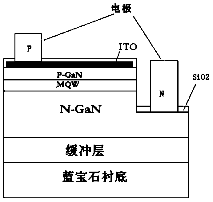
technical field [0001] The invention relates to the technical field of light emitting devices, in particular to an LED chip and a preparation method thereof. Background technique [0002] LED (Lighting Emitting Diode, light-emitting diode) chip is the core structure of LED. At present, most LED chips use sapphire as the substrate, such as figure 1 As shown, the chip structure includes: (1), respectively depositing epitaxial layers on the sapphire substrate material, from bottom to top are buffer layer, N-type GaN layer, MQW (Multiple Quantum Wells, multiple quantum wells) light-emitting layer, P type GaN layer. (2) Etching the chip from the P-type GaN layer to the N-type GaN layer, and preparing an N electrode, that is, a negative electrode, on the etched area. (3) An ITO (Indium tin oxide, indium tin oxide) layer is deposited on the P-type GaN layer, and a P electrode, that is, a positive electrode, is prepared on the ITO layer, wherein the ITO layer includes a silicon di...

Claims


Application Information

Patent Timeline
Patent Type & Authority Patents(China)
IPC IPC(8): H01L33/38H01L33/00
Inventor 张杰彭遥
Owner BYD SEMICON CO LTD
Learn More