Liquid cooling heat dissipation device and liquid cooling heat dissipation temperature control method

A technology of liquid-cooled heat dissipation and liquid-cooled head, which is applied in the direction of temperature control, instrumentation, and electrical digital data processing by using electric methods, and can solve the problem of reducing the operating power of fans and pumps, the inability to adjust the operating power of fans and pumps, and heat dissipation Insufficient heat dissipation efficiency and other problems, to avoid the effect of ineffective heat dissipation

Active Publication Date: 2017-12-08
GIGA BYTE TECH CO LTD
View PDF7 Cites 0 Cited by
  • Summary
  • Abstract
  • Description
  • Claims
  • Application Information

AI Technical Summary

Problems solved by technology

The above two modes only detect the temperature of the heat source (such as CPU, graphics chip). When the temperature exceeds the warning value, the fan and the pump will run at full speed at the same time; when the temperature is lower than the warning value, the fan and the pump will reduce the operation power
[0004] However, in common water cooling devices, the user cannot adjust the operating power of the fan and the pump, only in two low-power modes and high-power modes
In the low power mode, although the fan and the pump reduce the operating power, individual users have different feelings about the noise level of the fan and the pump, and the computer case itself may amplify the noise of either the fan or the pump due to resonance
[0005] However, if the user is directly involved in the fan or pump speed switching, the heat dissipation efficiency may be poor or the coolant flow may be insufficient, and the operating state may be quickly switched to a high power mode.

Method used


Image

  • Liquid cooling heat dissipation device and liquid cooling heat dissipation temperature control method
  • Liquid cooling heat dissipation device and liquid cooling heat dissipation temperature control method
  • Liquid cooling heat dissipation device and liquid cooling heat dissipation temperature control method

Examples


Embodiment Construction

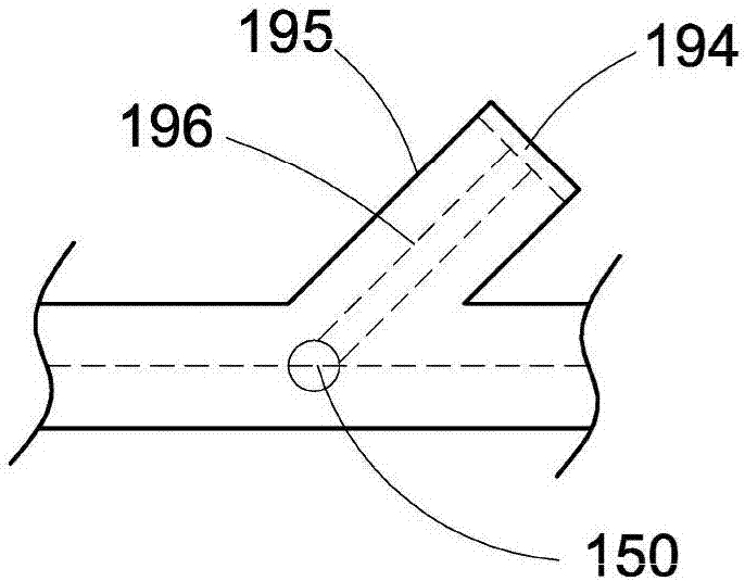
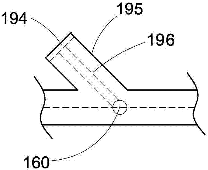
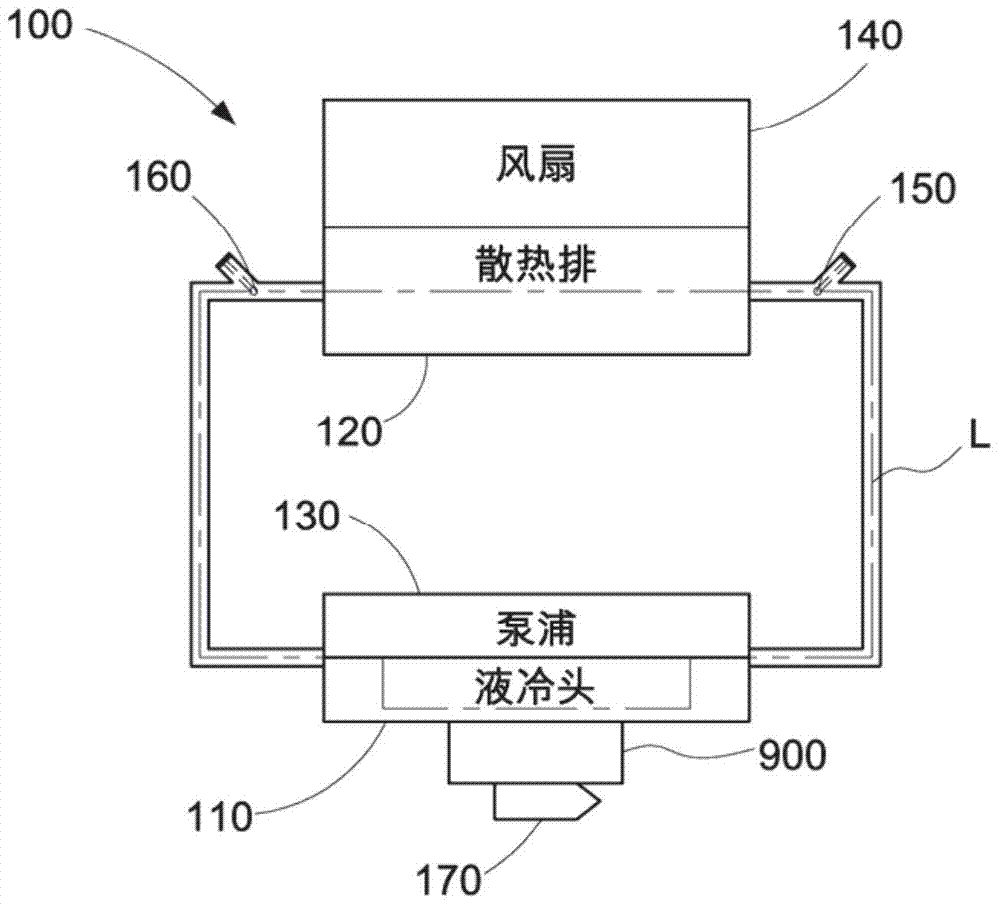
[0023] see figure 1 , figure 2 , image 3 and Figure 4 As shown, a liquid-cooled heat dissipation device 100 disclosed in an embodiment of the present invention is used for pumping a cooling liquid to cool a heat source 900 . The aforementioned heat source 900 includes but is not limited to a high-power integrated circuit chip (such as a central processing unit or a graphics chip). The liquid cooling heat dissipation device 100 includes a liquid cooling head 110, a radiator 120, a pump 130, at least one fan 140, a liquid inlet temperature device 150, a liquid outlet temperature device 160, a heat source temperature sensing device 170 and A control unit 180 .

[0024] Such as figure 1 As shown, the liquid cooling head 110 is usually a metal block or other blocks with thermal conductivity to conduct heat quickly. The liquid cooling head 110 is used to contact the heat source 900 to absorb the heat generated by the heat source 900 . The liquid cooling head 110 has at lea...


PUM


Abstract

A liquid-cooling heat dissipation device is used for implementing a liquid-cooling heat dissipation temperature control method to pump a cooling liquid to cool a heat source. The liquid-cooled heat dissipation temperature control method includes contacting a heat source with a liquid cooling head to absorb the heat generated by the heat source, and allowing the cooling liquid to pass through for heat exchange; connecting a heat sink to the liquid cooling head to form a cooling liquid circulation Flowing circulation pipeline; detect the temperature of the heat source, the inlet liquid temperature of the heat sink, and the liquid outlet temperature of the heat sink; judge whether the temperature of the heat source is greater than a high temperature warning value, and calculate the temperature between the liquid outlet temperature and the liquid inlet temperature Difference. When the temperature of the heat source is not greater than the high temperature warning value, the method adjusts the forced cooling efficiency of the radiator or the flow rate of the pumped cooling liquid according to the temperature difference, so as to meet the temperature control requirements and noise control.

Description

technical field [0001] The invention relates to liquid cooling technology, in particular to a liquid cooling device and a liquid cooling control method applied to computer devices. Background technique [0002] A water-cooling heat dissipation device for a computer mainframe usually includes a radiator connected to a pump and a water-cooling head, and a fan is used to strongly cool the radiator. Under the aforementioned structure, the main noise of the water-cooled heat sink comes from the operation of the pump, the flow of the coolant, and the rotation of the fan. [0003] The water cooling device is usually set to operate in two modes: low power mode and high power mode. The above two modes only detect the temperature of the heat source (such as CPU, graphics chip). When the temperature exceeds the warning value, the fan and the pump will run at full speed at the same time; when the temperature is lower than the warning value, the fan and the pump will reduce the operatio...

Claims


Application Information

Patent Timeline
Patent Type & Authority Patents(China)
IPC IPC(8): G06F1/20G05D23/19
Inventor 黄顺治林英宇
Owner GIGA BYTE TECH CO LTD
Why Eureka
Try Eureka