
CNC vision aided machining system and method

An auxiliary processing and vision technology, applied in metal processing equipment, metal processing machinery parts, manufacturing tools, etc., can solve the problem of low workpiece processing yield, and achieve the effect of reducing R&D and production costs, low requirements, and high intelligence

Inactive Publication Date: 2015-06-03
SUZHOU GUOZHIFU AUTOMATION EQUIP
View PDF8 Cites 13 Cited by
  • Summary
  • Abstract
  • Description
  • Claims
  • Application Information

AI Technical Summary

Problems solved by technology

[0005] In order to solve at least one of the above-mentioned technical problems, the object of the present invention is to provide a CNC visual aided processing system and method, which can accurately and quickly measure the contour of the workpiece, so that the CNC can also correctly process the deformable workpiece, and can avoid Contour defects, so as to solve the problem of low processing yield of easily deformed workpieces

Method used


Image

  • CNC vision aided machining system and method
  • CNC vision aided machining system and method

Examples


Embodiment Construction

[0039] The present invention will be described in detail below in conjunction with specific embodiments shown in the accompanying drawings. However, these embodiments do not limit the present invention, and any structural, method, or functional changes made by those skilled in the art according to these embodiments are included in the protection scope of the present invention.

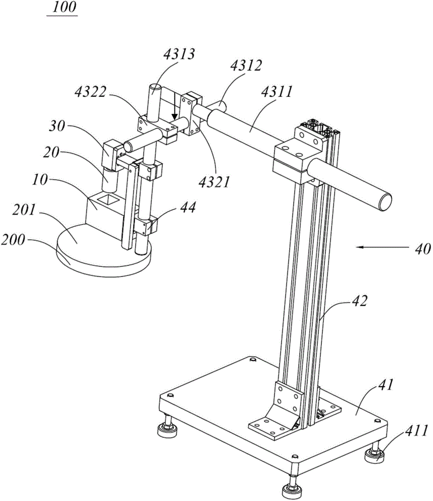
[0040] see figure 1 , figure 1 It is a schematic diagram of a CNC vision-assisted processing system according to an embodiment of the present invention. The CNC is used to process the workpiece 200 , and the CNC visual aided processing system 100 is mainly used to assist the CNC to complete the processing of the workpiece 200 . The CNC vision aided processing system 100 includes a light source assembly 10 disposed above the workpiece 200 , and the light source assembly 10 can emit parallel light to the upper surface 201 of the workpiece 200 . The CNC vision aided processing system 100 also includes ...


PUM


Abstract

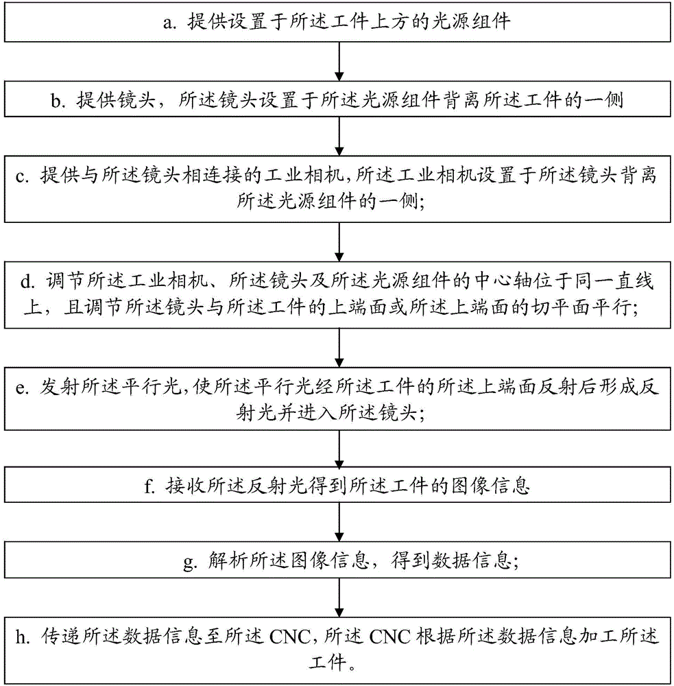
The invention discloses a CNC vision aided machining system and method. A CNC is applied to workpiece machining. The system comprises a light source component, a lens, an industrial camera and an industrial computer. The light source component is arranged above a workpiece and emits parallel light to the upper end surface; the lens is arranged on one side of the light source component far from the workpiece and is parallel to the upper end surface; the industrial camera is arranged on one side of the lens far from the light source component and is connected to the lens; the industrial computer is in information interaction with the industrial camera; the axle of the industrial camera, lens and light source component are located on one straight line; the parallel light penetrates the upper end surface to turn into reflection light and enter the lens, the industrial camera acquires image information and transmits image information to the industrial computer, the industrial computer analyzes the image information, acquires data information and transmits to the CNC, and the CNC machines the workpiece according to the data information. The system has the advantages that speed is high, operating time is saved, operating efficiency is improved, accuracy is high, product qualified rate is increased, and the machining cost for positioning a jig is saved.

Description

technical field [0001] The invention relates to a CNC visual aided processing system and method, and belongs to the technical field of mechanical processing and visual imaging analysis. Background technique [0002] Said CNC is the abbreviation of Computer Numerical Control in English, and its Chinese translation is: CNC machining center, CNC machine tool is a highly automated multifunctional CNC machine tool with tool magazine and automatic tool changer. After the workpiece is clamped once, CNC can complete multiple processes on more than two surfaces, and has multiple tool change or tool selection functions, reducing manual operations, not only improving production efficiency, but also ensuring processing quality. However, when CNC processes easily deformable parts according to the preset tool path, there is no way to process good products, especially when processing the edge contours of easily deformable parts. [0003] In the prior art, the use of numerical control prob...

Claims


Application Information

Patent Timeline
Patent Type & Authority Applications(China)
IPC IPC(8): B23Q17/24
CPCB23Q17/2409B23Q17/2471
Inventor 郭景忠
Owner SUZHOU GUOZHIFU AUTOMATION EQUIP
Learn More