
Automatic arranging device for chip injection molding machine

An injection molding machine and automatic technology, applied in sports accessories, roulette games, indoor games, etc., can solve problems such as rising production costs, personal safety hazards, slow placement speed, etc., achieve reliable work, improve automation level, and place speed up effect

Active Publication Date: 2015-06-03
桐乡市洲泉振强塑业股份有限公司
View PDF3 Cites 3 Cited by
  • Summary
  • Abstract
  • Description
  • Claims
  • Application Information

AI Technical Summary

Problems solved by technology

[0002] This equipment is widely used in machinery manufacturing, metallurgy, electronics, light industry and atomic energy manufacturing; the traditional injection molding method is to manually screen and place inserts for injection molding. The efficiency is not high, and it is also accompanied by the occurrence of accidents and the crisis of personal safety, which directly lead to the increase of the production cost of the enterprise

Method used


Image

  • Automatic arranging device for chip injection molding machine
  • Automatic arranging device for chip injection molding machine
  • Automatic arranging device for chip injection molding machine

Examples


Embodiment 1

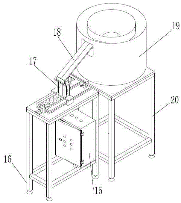
[0015] Such as figure 1 As shown, the automatic placement equipment of the chip injection molding machine described in this embodiment includes a first frame 16 and a second frame 20, and the first frame 16 is provided with a fixed support plate 1 and an electric control box 15 , the fixed support plate 1 is provided with an automatic placement mechanism 17, and the automatic placement mechanism 17 is provided with a guide tube 9; the second frame 20 is provided with a vibrating plate 19, and the vibrating plate 19 A guide mechanism 18 is provided at the place, and one end of the guide mechanism 18 is connected with one end of the guide tube 9, and the electric control box 15 is electrically connected with the automatic placement mechanism 17 and the vibrating plate 19; 15 Make the vibrating plate 19 vibrate, and the inserts vibrate out from the discharge port along the guide mechanism and enter the guide tube 9 in the automatic swing mechanism, so that the inserts are stacked...

Embodiment 2

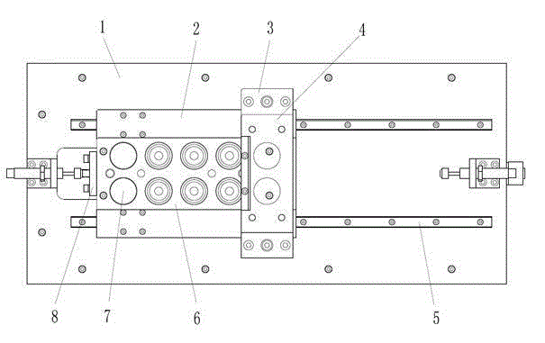
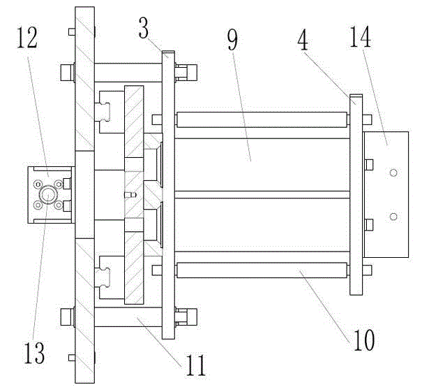
[0018] Such as figure 2 , image 3 As shown, the automatic placement equipment of the chip injection molding machine described in this embodiment is different from Embodiment 1 in that the automatic placement mechanism 17 includes a fixed plate backing plate 2, a collision block 8, a round tube lower pressure plate 3, a round tube Upper platen 4, platen seat 11, studs 10, cylinder piston rod 13 and product fixing plate 6; the fixed support plate 1 is provided with a ball linear guide 5, and the ball linear guide 5 is movably connected to the fixed plate backing plate 2 ; The two ends of the plate base 11 are supported and fixed between the fixed support plate 1 and the lower platen 3 of the circular tube; the guide tube 9 is located between the upper platen 4 of the circular tube and the lower platen 3 of the circular tube, through The stud 10 connects the upper platen 4 of the round pipe and the lower platen 3 of the round pipe to compress the guiding round pipe 9; the uppe...


PUM


Abstract

The invention discloses an automatic arranging device for a chip injection molding machine. The device comprises a first rack and a second rack. The device is characterized in that a fixation support plate and an electric control cabinet are arranged on the first rack, an automatic arranging mechanism is arranged on the fixation support plate, and a guide round tube is arranged in the automatic arranging mechanism. A vibration disc is arranged on the second rack, a guide mechanism is arranged on the vibration disc, one end of the guide mechanism is communicated with one end of the guide round tube, and the electric control cabinet is electrically connected with the automatic arranging mechanism and the vibration disc. The device has the advantages of being fast in screening and arranging, reliable in operation, high in efficiency, reliable in operation performance and capable of reducing the cost and improving the automation degree.

Description

technical field [0001] The invention relates to an injection molding machine, in particular to an automatic placement device for a chip injection molding machine. Background technique [0002] This equipment is widely used in machinery manufacturing, metallurgy, electronics, light industry and atomic energy manufacturing; the traditional injection molding method is to manually screen and place inserts for injection molding. The placement speed is slow when placed manually, and it needs to be placed one by one. The efficiency is not high, and it is accompanied by the occurrence of accidents and the crisis of personal safety, which directly lead to the increase of the production cost of the enterprise. Contents of the invention [0003] The object of the present invention is to solve the above technical deficiencies and design an automatic placement device for chip injection molding machines that improves work efficiency and reduces costs. [0004] The automatic placemen...

Claims


Application Information

Patent Timeline
Patent Type & Authority Applications(China)
IPC IPC(8): A63F9/00A63F5/00
Inventor 徐建
Owner 桐乡市洲泉振强塑业股份有限公司
Learn More