Rotor of rotating motor

A technology of rotating electrical machines and rotors, which is applied in the field of parallel rotating electrical machine rotors, can solve the problems of high manufacturing process and manufacturing cost, high manufacturing cost, high mechanical strength of rotor punching, and achieve the effect of reducing usage and cost

Inactive Publication Date: 2015-05-27
澳特卡新能源科技(上海)有限公司
View PDF6 Cites 6 Cited by
  • Summary
  • Abstract
  • Description
  • Claims
  • Application Information

AI Technical Summary

Problems solved by technology

The radial magnetic flux leakage coefficient is small, the shaft does not need to take magnetic isolation measures, and the mechanical strength of the rotor plate is high; the tangential magnetic flux leakage coefficient is large, and corresponding magnetic isolation measures are required. The manufacturing process and manufacturing cost of the motor are lower than radial The advantage is that the magnetic flux under one pole pitch is provided by two adjacent magnetic poles in parallel, and a larger magnetic flux per pole can be obtained; the hybrid structure combines the advantages of radial and tangential rotor structures, but the structure And the manufacturing process is more complicated, and the manufacturing cost is higher

Method used


Image

  • Rotor of rotating motor
  • Rotor of rotating motor
  • Rotor of rotating motor

Examples


Embodiment 1

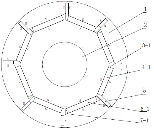
[0022] see figure 1 , the rotor of the rotating electrical machine of the present invention includes a rotating shaft 2 and a rotor core 1, a number of NdFeB magnets 5 are evenly and tangentially built in the rotor core 1, and iron is built radially between two adjacent NdFeB magnets 5. Ferrite magnets 4-1, 6-1; the adjacent NdFeB magnets 5 are arranged in N and N relative arrangements, and the adjacent ferrite magnets 4-1 and 6-1 are arranged with N and S intervals The way it is arranged.

[0023] In order to reasonably accommodate the magnets, a number of first-type slots 3-1 and second-type slots 7-1 are formed in the rotor core 1 and are evenly distributed and spaced apart. Among them, the first type of slot 3-1 includes a linear bottom slot and side slots, the second type of slot 7-1 is linear, and the NdFeB magnet 5 is placed in the side slot of the first type of slot 3-1 Inside, the ferrite magnets 4-1, 6-1 are placed in the bottom groove of the first type of slot 3-1...

Embodiment 2

[0026] see image 3 , the rotor structure of this embodiment is roughly the same as that of Embodiment 1, the difference mainly lies in that a third type of slot 3- 2, 7-2, ferrite magnets 4-2, 6-2 are built-in in the third type slot holes 3-2, 7-2, so that ferrite magnets 4-1, 4-2 , 6-1, 6-2 are double-layer structures. Such as Figure 4 As shown, the tangential NdFeB magnets 5 alone provide magnetic flux, and the radial ferrite magnets 4-1, 4-2, 6-1, 6-2 are connected in series to provide magnetic flux together. Specifically The magnetic flux goes as Figure 4 shown.

[0027] To sum up, in view of the fact that the tangential NdFeB permanent magnets and the radial ferrite permanent magnets provide magnetic flux in parallel, the magnetic potentials of the two need to be kept consistent. In the actual application process, the residual magnetic induction of NdFeB magnet 5 B r is generally around 1.2T, the coercive force is around 907kA / m, and the residual magnetic inducti...


PUM

PropertyMeasurementUnit
magnetic flux densityaaaaaaaaaa

Abstract

The invention discloses a rotor of a rotating motor. The rotor comprises a rotating shaft and a rotor core, wherein a plurality of pieces of neodymium iron boron magnetic steel are uniformly embedded in the rotor core in tangential directions; a piece of ferrite magnetic steel is embedded between two adjacent pieces of neodymium iron boron magnetic steel in a radial direction; two adjacent pieces of neodymium iron boron magnetic steel are arranged in an N-N opposite manner; two adjacent pieces of ferrite magnetic steel are arranged in an N-S separating manner. The rotor has the benefits that the ferrite magnetic steel and reluctance torque are sufficiently utilized, so that the consumption of the neodymium iron boron magnetic steel can be greatly reduced under the premise that motor output torque is guaranteed. Therefore, the cost of a permanent magnet motor can be reduced.

Description

technical field [0001] The invention relates to a rotating electrical machine rotor, in particular to a parallel rotating electrical machine rotor utilizing ferrite magnetic steel and neodymium-iron-boron magnetic steel. Background technique [0002] Permanent magnet motors have attracted more and more attention due to their advantages such as high power density and high efficiency. However, the price of high-performance permanent magnet material NdFeB continues to rise, making many research institutions and motor manufacturers begin to shift their research direction to the technical field that at least uses NdFeB or does not use NdFeB. [0003] According to the relationship between the magnetization direction of the permanent magnet steel and the rotation direction of the rotor, the built-in permanent magnet has three types of rotor magnetic circuit structures: radial type, tangential type, and hybrid type. The radial magnetic flux leakage coefficient is small, the shaft d...

Claims


Application Information

Patent Timeline
Patent Type & Authority Applications(China)
IPC IPC(8): H02K1/27
CPCH02K1/2766
Inventor 张胜川高晓杰牛敬彬徐婷婷
Owner 澳特卡新能源科技(上海)有限公司
Why Eureka
Try Eureka