A method of manufacturing a hemispherical Lunberg lens antenna

A technology of Lunberg lens antenna and lens antenna, applied in the field of communication, can solve the problems of difficult control of dielectric constant tolerance, dielectric constant fluctuation, product performance and expected deviation, and achieve good social and economic benefits, simple production process, The effect of stable product quality

Active Publication Date: 2017-08-04
AEROSPACE INST OF ADVANCED MATERIALS & PROCESSING TECH
View PDF2 Cites 0 Cited by
  • Summary
  • Abstract
  • Description
  • Claims
  • Application Information

AI Technical Summary

Problems solved by technology

However, when the foam density reaches the expected value during foaming, it only means that the macroscopic average dielectric constant of the whole foam reaches the expected value. Due to the characteristics of the foaming process, it is difficult to ensure that the material is uniform at the micro level. There are a large number of bubbles that are too large or too small, so that the dielectric constant fluctuates microscopically, causing product performance to deviate from expectations, and the degree of performance deviation of different batches of products is also different. In addition, according to the scattering effect, when the foam When the diameter of the inner bubble is greater than one-third of the incident wavelength, it will also cause a significant decrease in the performance of the Lunberg lens
At the same time, the foaming method may cause secondary foaming of the beads during the molding process, making it difficult to control the dielectric constant and reduce the uniformity
In addition, the foam material shrinks after the mold cools, resulting in an air gap between adjacent spherical shells during assembly, which has a greater impact on the performance of the lens
Therefore, the foaming method has problems that are difficult to control the tolerance of the dielectric constant and the interior is not easy to be uniform.
[0013] As a dielectric passive device, Lunberg lens antenna has the advantages of small size, light weight, large radar cross-sectional area, large pattern and wide spectrum width, but its manufacturing process is difficult, tedious, time-consuming, costly, and consistent. Poor performance, which limits its promotion and application

Method used


Image

  • A method of manufacturing a hemispherical Lunberg lens antenna
  • A method of manufacturing a hemispherical Lunberg lens antenna

Examples


Embodiment 1

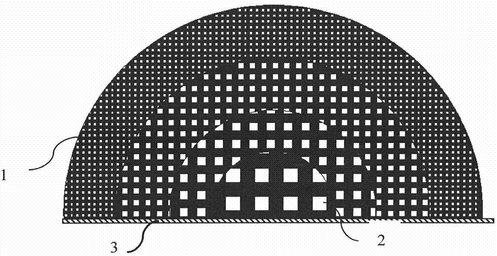
[0081] The hemispherical Lunberg lens antenna made in this embodiment is a hemisphere, in which cavities are distributed, the radius R of the sphere is 60mm, the target RCS value is greater than or equal to 0dBsm, the target incident electromagnetic wave is 9.4GHz, the wavelength is 32mm, and the cavity is A regular hexahedron with a side length of 3.5 mm and a metal foil layer thickness of 0.2 mm.

[0082] In this embodiment, PLA is selected as the material for making the hemispherical Lunberg lens antenna, and its dielectric constant is 2.5. Then use the formula ε i =2-(r i / R) 2 Calculate the dielectric constant of each concentric layer; then calculate the cavity volume fraction of each concentric layer according to the following formula: the average dielectric constant of each concentric layer=[the dielectric constant of this concentric layer material × (1-all in this concentric layer cavities in the concentric layer) + the dielectric constant of the cavity medium × the...


PUM


Abstract

The invention discloses a manufacturing method of a hemispherical Lunberian lens antenna. The hemispherical Lunberian lens antenna is distributed with cavities, has a hemispherical surface and a bottom plane, and the bottom plane is a plane passing through the center of the sphere; it is characterized in that the Described method comprises the steps: (1) select the material that is used to manufacture hemispherical Lunberg lens antenna; (2) determine the structural parameter of hemispherical Lunberg lens antenna; (3) make the hemispherical Lunberg lens antenna with described structural parameter A three-dimensional digital model; and (4) manufacturing the hemispherical Lunberg lens antenna according to the three-dimensional digital model by using an additive manufacturing method; and (5) pasting a metal foil layer on the bottom plane. The shape, size and distribution of the cavity structure in the hemispherical Lunberg lens antenna produced by the present invention are adjustable and controllable, which realizes the precise control of the average dielectric constant of the concentric layer and can meet different design requirements; and the production materials are widely used , The production process is simple, the yield is high, and there is no gap between layers, which makes the product quality more stable and reliable.

Description

technical field [0001] The invention relates to the communication field, and more specifically, relates to a hemispherical Lunberg lens antenna. Background technique [0002] The basic shape of the Lunberg lens antenna is a sphere (sometimes referred to as a Lunberg sphere in this paper), which is a concept proposed by R.K. Lunberg in 1944 based on the geometrical optics method. A Luneberg lens antenna is a lens antenna that focuses electromagnetic waves to a focal point through a dielectric. It is a sphere made of dielectric material that can focus electromagnetic waves coming from all directions to a corresponding point on the surface of the lens. In the part infinitely close to the surface of the sphere, the dielectric constant of the material=1 (that is, the same as the dielectric constant of air), and the dielectric constant=2 at the center of the sphere. The dielectric constant of the material from the surface to the center of the sphere changes gradually, and its va...

Claims


Application Information

Patent Timeline
Patent Type & Authority Patents(China)
IPC IPC(8): H01Q15/02H01Q19/06
Inventor 周勇邢孟达赵宏杰
Owner AEROSPACE INST OF ADVANCED MATERIALS & PROCESSING TECH
Why Eureka
Try Eureka