
Brick cutter for cement rotary kiln firebrick

A cement rotary kiln and refractory brick technology, applied in stone processing equipment, grinding machines, grinding/polishing equipment, etc., can solve problems such as time-consuming, inconvenient consignment, and physical hazards for operators

Inactive Publication Date: 2015-05-27
ANHUI WUHU CONCH CONSTR & INSTALLATION ENG
View PDF6 Cites 1 Cited by
  • Summary
  • Abstract
  • Description
  • Claims
  • Application Information

AI Technical Summary

Problems solved by technology

[0003] The traditional brick cutting machine is imported from Germany. The equipment is relatively large, weighing up to 5 tons, and requires a special machine room, which is inconvenient for consignment;
[0004] The traditional brick cutting machine is placed in a special machine room, and the refractory bricks need to be transported back and forth during the processing process, which is labor-intensive and time-consuming. In addition, the traditional brick cutting machine has a lot of dust during processing, which is a potential hazard to the operator's body

Method used


Image

  • Brick cutter for cement rotary kiln firebrick
  • Brick cutter for cement rotary kiln firebrick
  • Brick cutter for cement rotary kiln firebrick

Examples


Embodiment 1

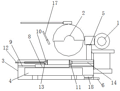
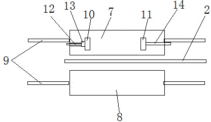
[0017] Such as figure 1 , 2 As shown, a brick cutter suitable for refractory bricks in a cement rotary kiln includes a motor 1 and a cutting wheel 2 driven by the motor, and a water shower nozzle 17 is provided at the same time. The vertical position of the lower part of the cutting wheel 2 is provided with a brick cutting Bracket 3, the brick body cutting bracket 3 is provided with a brick body fixing platform 4, and the brick body clamping structure on the brick body fixing platform is provided between the cutting wheel 2 and the brick body cutting bracket 3 A dust collector 5, and a dust suction pipe 6 is also arranged in the brick body cutting pallet 3 . The dust collector 5 is a rectangle and is hollowed out to the side and bottom of the cutting wheel 2 . The dust collector 5 collects the cutting dust and falls into the collection port 18 of the dust suction pipe 6 .

[0018] Described brick body fixed platform comprises left fixed platform 7, right fixed platform 8, an...

Embodiment 2

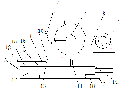
[0020] Example 2, such as image 3 As shown, on the basis of Embodiment 1, for the convenience of cutting and adjustment, a sliding rod 15 is arranged in the left fixed platform 7 and the right fixed platform 8, and is arranged at the left end of the left fixed platform 7 and the right fixed platform 8 There is a linkage pull rod 16.

[0021] The weight of the brick cutter is only 200 kg, and it is convenient for consignment; it is convenient to operate, reduces the workload of refractory bricks back and forth, reduces labor costs, and is equipped with a clamping device, so that the processing quality can meet the requirements of masonry; the addition of a dust collection device makes the processing When the dust is greatly reduced, the body of the operator is protected from injury;


PUM


Abstract

The invention discloses a brick cutter for a cement rotary kiln firebrick. The brick cutter for the cement rotary kiln firebrick comprises a motor and an abrasive cutting wheel, and is characterized in that a brick body cutting support bench is arranged on the lower part of the abrasive cutting wheel; a brick body fixing bench is arranged in the brick body cutting support bench; a brick body clamping structure is arranged on the upper part of the brick body fixing bench; a dust collector is arranged between the abrasive cutting wheel and the brick body cutting support bench; a dust exhaust pipeline is also arranged in the brick body cutting support bench. The brick cutter for the cement rotary kiln firebrick has the beneficial effects that the weight of the brick cutter is only 200 kg, and the brick cutter is more convenient to transport; the operation is convenient, the workload of transporting the firebricks back and forth is reduced, the labor cost is reduced, and the processing quality can meet the masonry requirement as the clamping device is adopted; the quantity of dust is greatly reduced due to the dust collector, and the health of operators is protected from being harmed.

Description

technical field [0001] The invention relates to a cement rotary kiln processing equipment, in particular to a brick cutter suitable for refractory bricks of the cement rotary kiln. Background technique [0002] At present, the main function of the rotary kiln refractory brick is to protect the kiln shell from the damage of high-temperature gas and high-temperature materials, and to ensure the normal production. During the clinker calcination process, because the gas temperature in the kiln is much higher than the material temperature, every time the kiln rotates, the surface of the kiln lining is subject to periodic thermal shocks, and the temperature range is 150°C to 250°C. Thermal stress occurs within the 20mm surface range. The kiln lining also bears the alternating radial and axial mechanical stress of the brick masonry due to the rotation of the kiln, as well as the erosion and wear of the calcined materials. Due to the simultaneous production of silicate melt, i...

Claims


Application Information

Patent Timeline
IPC IPC(8): B28D1/22B28D7/02B24B27/06
CPCB24B27/06B24B41/06B24B55/06
Inventor 舒银军
Owner ANHUI WUHU CONCH CONSTR & INSTALLATION ENG
Learn More