
Piezoelectric Microgripper Based on Flexible Hinge Amplification

A flexible hinge and micro-clamp technology, applied in the field of micro-clamps, can solve the problems that the displacement cannot be directly related, the position of the lever fulcrum is not clear, and it is difficult to integrate into the micro-operating system. Small, wide-ranging effects

Inactive Publication Date: 2016-08-24
ZHEJIANG UNIV
View PDF7 Cites 3 Cited by
  • Summary
  • Abstract
  • Description
  • Claims
  • Application Information

AI Technical Summary

Problems solved by technology

The shortcoming of this micro-clamp is: 1, left and right second rigid beams are arranged by the hinge dislocation of its two ends, thereby make the second rigid beams form lever, but the lever fulcrum position that the second rigid beams forms is not clear, its Magnification effect is not obvious and indeterminate
2. The movement of the left and right rigid beams is transmitted to the left and right first rigid beams through the left and right flexible beams, and the deformation of the flexible beams may absorb part of the amplified displacement, resulting in the deformation of the piezoelectric ceramic driver and the chuck. The displacement cannot be directly related, so the clamping force and position of the collet must be detected by visual detection, laser sensor detection or capacitance detection. The detection cost is high and it is difficult to integrate into the micro-operating system.

Method used


Image

  • Piezoelectric Microgripper Based on Flexible Hinge Amplification
  • Piezoelectric Microgripper Based on Flexible Hinge Amplification
  • Piezoelectric Microgripper Based on Flexible Hinge Amplification

Examples


Embodiment Construction

[0030] With reference to accompanying drawing, further illustrate the present invention:

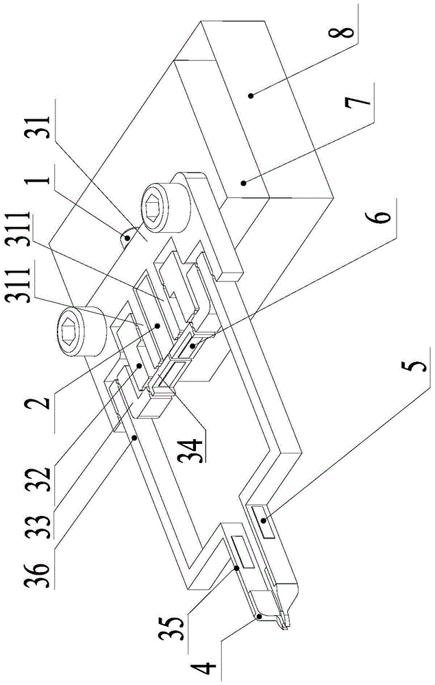
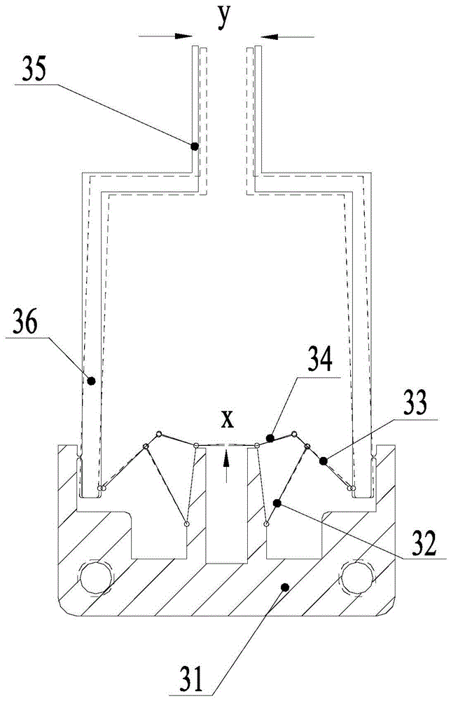
[0031] Such as figure 1As shown, the piezoelectric micro-clamp based on flexible hinge amplification includes a base, a frame 31 fixed on the base, a piezoelectric stack driver 2 is installed on the frame 31, and the pretension of the piezoelectric stack driver 2 Screw 1, motion transmission mechanism, a pair of clamping arms 35 and chucks mounted on the head ends of the clamping arms 35, the motion transmission mechanism converts the deformation of the piezoelectric stack driver 2 into the displacement of the clamping head 4; the frame 31 has a For the symmetrically arranged columns 331, the piezoelectric stack driver 2 is located between the two columns 331; the motion transmission mechanism includes a pair of double rocker mechanisms and a pair of lever arms 36 symmetrically arranged on both sides of the piezoelectric stack driver 2 One end of the active rocker 34 of the double rocke...


PUM


Abstract

The invention discloses a flexible hinge amplification-based piezoelectric microgripper, which comprises a substrate, a rack, a piezoelectric stack driver, a pre-tightening screw, a motion transmission mechanism, a pair of clamping arms and a chuck; the deformation of the piezoelectric stack driver is converted into the displacement of the chuck by the motion transmission mechanism; the rack is provided with two pillars, and the piezoelectric stack driver is located between the two pillars; the motion transmission mechanism comprises a pair of double-rocker mechanisms and a pair of lever support arms; one end of an active rocker of each double-rocker mechanism is hinged with the corresponding pillar, and the other end of the active rocker is hinged with a corresponding connecting rod; each active rocker is provided with an extension section; the extension sections of the active rockers lean against the piezoelectric stack driver; the deformation of the piezoelectric stack driver serves as the driving force of each double-rocker mechanism; a position detection strain gage is adhered to the extension section of the corresponding active rocker; each clamping arm is provided with a clamping force detection strain gage. The flexible hinge amplification-based piezoelectric microgripper disclosed by the invention has the advantages that not only can the large stroke of the tail end of the microgripper be realized but also the clamping force detection and the position detection of the tail end of the microgripper can be integrated.

Description

technical field [0001] The invention relates to a piezoelectric stack driven micro clamp. technical background [0002] As a key component of micro-electromechanical systems, micro-grippers are a basic tool for communicating the macroscopic and microscopic worlds. Micro-grippers can perform operations such as pick-up, clamping, and release, and are therefore widely used in micro-assembly, biomedicine, aerospace, and military and other fields. [0003] Compared with electrostatic comb drive, electrothermal drive and shape memory alloy drive, piezoelectric stack drive has the advantages of high resolution, large driving force, wide frequency response range, fast response speed and good dynamic characteristics, so it is especially suitable for to drive the microgripper. In the field of micro-assembly technology, it is often necessary to use micro-grippers to operate irregular and fragile parts from the micro-nanometer level to the millimeter level. Therefore, the micro-grippe...

Claims


Application Information

Patent Timeline
Patent Type & Authority Patents(China)
IPC IPC(8): B25J7/00B25J15/08B25J19/02
Inventor 杨依领魏燕定武敏娄军强田埂金立帅
Owner ZHEJIANG UNIV
Learn More