
Mobile terminal

A mobile terminal and mobile technology, which is applied in the construction parts of electrical equipment, telephone communications, instruments, etc., can solve problems such as low cost, damage, and impact on product safety, and achieve low cost, improved safety, and improved heat dissipation efficiency. Effect

Inactive Publication Date: 2015-05-20
FUTAIHUA PRECISION ELECTRONICS ZHENGZHOU +1
View PDF11 Cites 17 Cited by
  • Summary
  • Abstract
  • Description
  • Claims
  • Application Information

AI Technical Summary

Problems solved by technology

[0002] Nowadays, mobile terminals (such as mobile phones, tablet computers, etc.) have more and more functions, and the power consumption is also increasing. It is inevitable that a lot of heat will be generated inside the mobile terminal. If the heat is not evacuated in time, the high temperature will damage the The electronic components inside the mobile terminal will reduce the service life of the mobile terminal, or even be directly damaged
[0003] In order to prevent the internal temperature of the mobile terminal from being too high, a prior art is to set a metal cover on the heating element, and attach a high thermal conductivity material to the outside of the metal cover, so that the heat generated by the heating element is conducted to the high thermal conductivity material through the metal cover. However, the high thermal conductivity material is not in direct contact with the external cold air, and the heat it carries still needs to be exchanged with the external cold air through the back cover of the mobile terminal, so the heat dissipation efficiency is not high, and the high thermal conductivity material is generally graphite sheet, Copper foil, etc., its cost is relatively high
[0004] Another existing technology is to dissipate heat by setting diversion holes, that is, guide the external cold air to the surface of the heating element for heat exchange through diversion settings. This method of heat dissipation does not require heat-conducting materials and has low cost. Insufficient heat dissipation area of ​​components leads to low heat dissipation efficiency, and this method will bring dust, fluid or water vapor into the product, seriously affecting the safety of the product

Method used


Image

  • Mobile terminal
  • Mobile terminal
  • Mobile terminal

Examples


Embodiment Construction

[0017] Embodiments according to the present invention will be described with reference to the drawings. These drawings are all simplified schematic diagrams, which only illustrate the basic structure of the present invention in a schematic manner, so they only show the configurations related to the present invention.

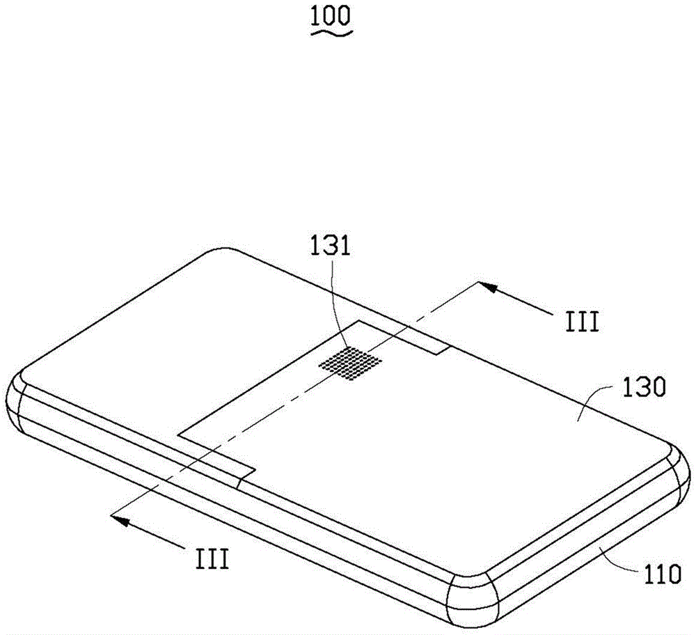
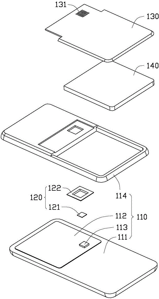
[0018] see figure 1 and figure 2 , the mobile terminal 100 in the first embodiment of the present invention includes a body 110 , a heat sink 120 and a rear cover 130 . The heat dissipation part 120 is disposed inside the body 110 and is covered by a rear cover 130 . The rear cover 130 is movably connected to the body 110 . The rear cover 130 can be a battery button cover for sealing the battery 140 .

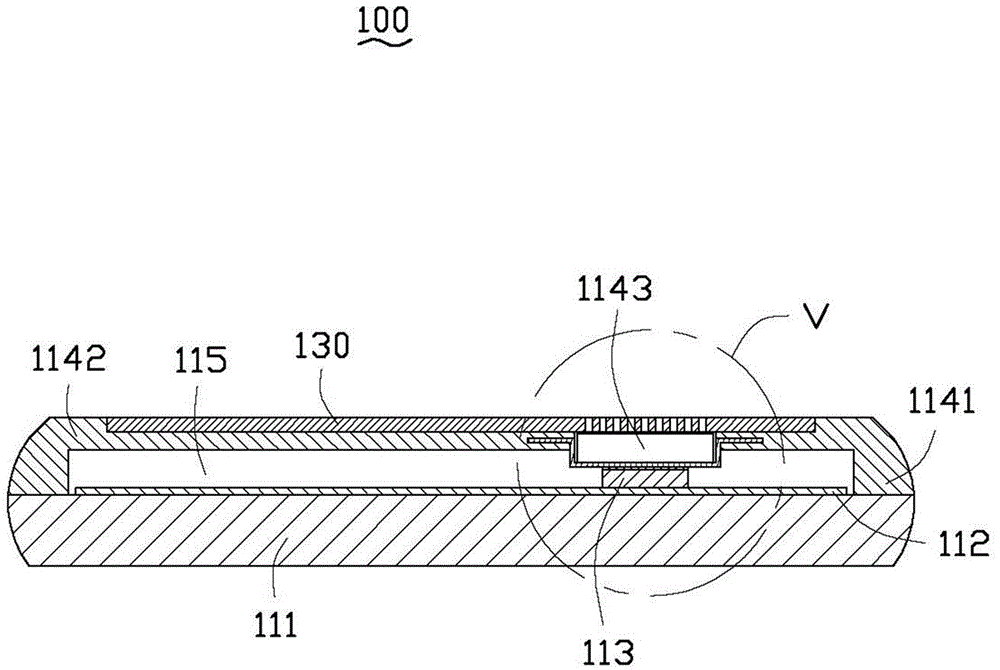
[0019] Please also refer to image 3 , the body 110 includes a front panel 111 , a circuit substrate 112 , a heating element 113 and a rear panel 114 . The front panel 111 can be used for installing components such as a display screen and buttons. The circu...


PUM


Abstract

A heat-dissipating mobile terminal includes a main body, a heat dissipating member positioned in the main body, and a back cover detachably connected to the main body. The main body includes a heat-producing element and the heat dissipating member includes a heat radiator arranged above the heat-producing element. The back cover defines a perforated portion above the heat dissipating member. The heat radiator is integrated with the main body. The heat radiator is exposed to external cooler air by the perforated portion in the back cover. The mobile terminal of the present disclosure effectively improves heat radiating efficiency and reduces cost.

Description

technical field [0001] The invention relates to a mobile terminal, in particular to a mobile terminal with a heat dissipation structure. Background technique [0002] Nowadays, mobile terminals (such as mobile phones, tablet computers, etc.) have more and more functions, and the power consumption is also increasing. It is inevitable that a lot of heat will be generated inside the mobile terminal. If the heat is not evacuated in time, the high temperature will damage the The electronic components inside the mobile terminal will reduce the service life of the mobile terminal, or even be directly damaged. [0003] In order to prevent the internal temperature of the mobile terminal from being too high, a prior art is to set a metal cover on the heating element, and attach a high thermal conductivity material to the outside of the metal cover, so that the heat generated by the heating element is conducted to the high thermal conductivity material through the metal cover. However...

Claims


Application Information

Patent Timeline
Patent Type & Authority Applications(China)
IPC IPC(8): H05K7/20G06F1/20
CPCG06F1/1626G06F1/1656G06F1/203H04M1/0202H04M1/21H05K7/20445
Inventor 章绍汉
Owner FUTAIHUA PRECISION ELECTRONICS ZHENGZHOU
Learn More