
Large reciprocating feeder

A reciprocating feeder technology, which is applied in the field of large reciprocating feeders, can solve the problems of difficulty in adjusting the stroke of the feeder, difficulty in reaching the operator, and insufficient strength of the feeder, so as to achieve balanced force and high performance. Excellent, rigidity-enhancing effect

Inactive Publication Date: 2015-05-20
何钢
View PDF0 Cites 2 Cited by
  • Summary
  • Abstract
  • Description
  • Claims
  • Application Information

AI Technical Summary

Problems solved by technology

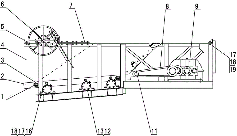
The disadvantages of the existing reciprocating feeder are: first, there is no underframe under the bin body of the feeder, and the underframe and bin body of the motor and reducer are welded together by section steel cable-staying, and cannot be connected with the motor and the bin body. The bottom frame under the reducer forms an integral steel structure. When the bin body is full of materials, the strength of the feeder is obviously insufficient.
Second, in order to rotate and adjust the rounded stroke of the feeder, the positioning dimensions of the crank and the crank hub on the crank connecting rod device must be decimals. In the process of processing, a small error will make the crank unable to rotate Pin hole centering on hub makes feeder travel difficult to adjust
Third, due to the self-weight of the fan-shaped adjustable gate, in order to facilitate the adjustment of the opening, a long cantilever extending out of the warehouse body and a counterweight are used to balance its self-weight. It is difficult for the operator to reach the position of the suspended counterweight when the feeder is hoisted and installed. to adjust the opening of the gate
Fourth, due to the reciprocating motion of the bottom plate, there must be a gap between it and the side plate, and the material will often be squeezed out from the gap, causing the feeder to leak material

Method used


Image

  • Large reciprocating feeder
  • Large reciprocating feeder
  • Large reciprocating feeder

Examples


Embodiment Construction

[0019] The present invention will be further described below in conjunction with accompanying drawing:

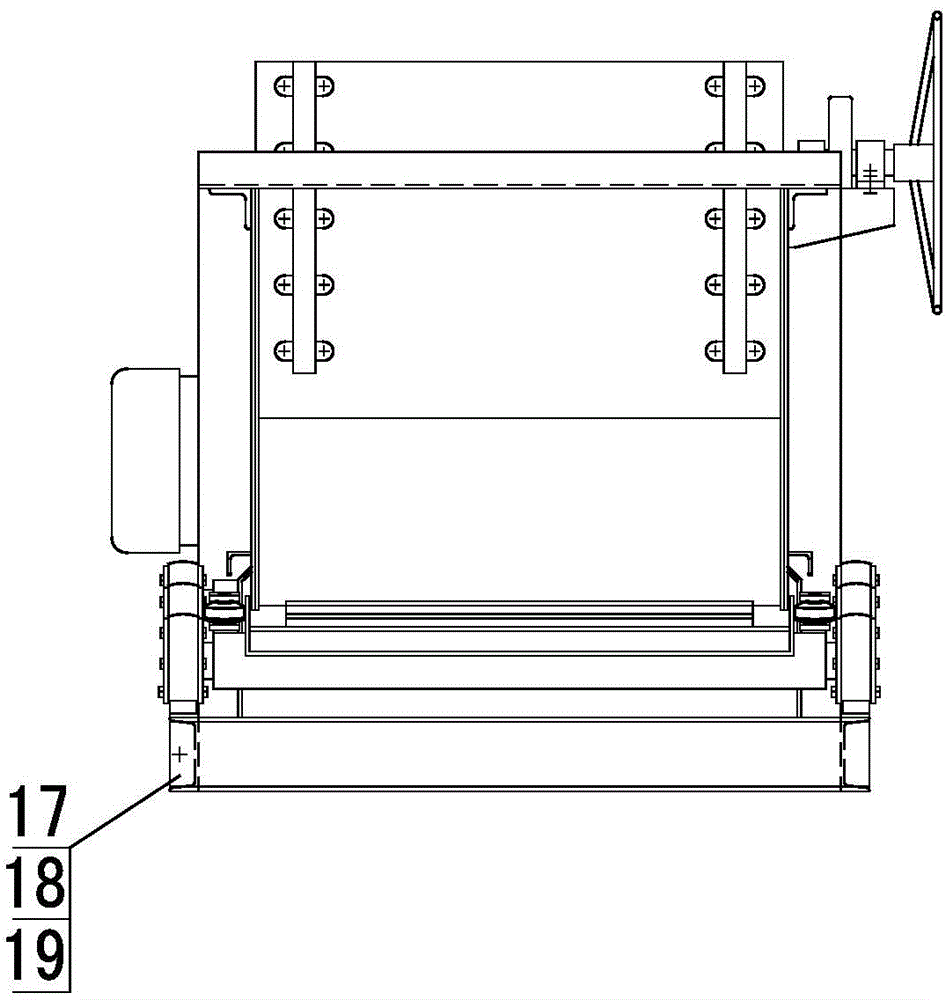
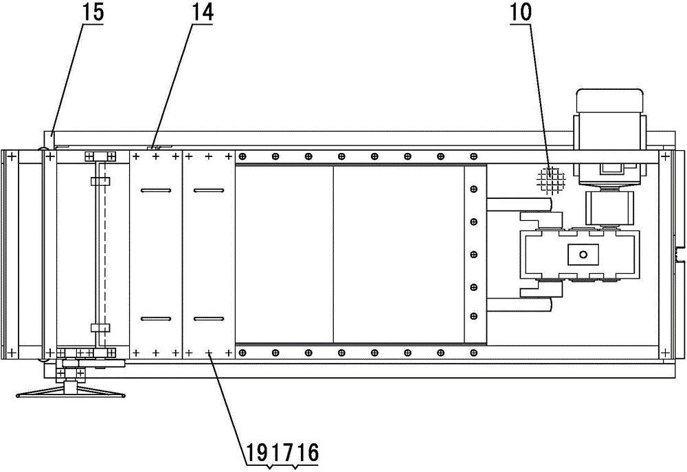
[0020] A large reciprocating feeder, such as attached Figure 1-3 As shown, it mainly includes a material guide trough, a support frame, a driving device 9, a bracket 3, a crank connecting rod device 8 and an adjustment gate 6, and the driving device 9 is connected to the crank connecting rod device 8 on one side of the material guide tank, and the crank connecting rod device 8 is connected to the crank connecting rod device 8. The rod device 8 is installed on the support frame, and the adjusting gate 6 is located at the discharge port of the material guide groove. The main assembly structure is that the feed trough is welded by steel plates into a semi-closed groove shape at the top, a cover plate 7 is arranged on the top of the feed trough, so that the feed trough is in a semi-closed state, and the cover plate 7 at the head end is formed by The hand wheel and the screw r...


PUM


Abstract

The invention relates to a large reciprocating feeder and belongs to the technical field of middle circulation and constant speed feeding of materials and feeding equipment suitable for material production systems and the industries such as metallurgical mines, building materials and electric power. The large reciprocating feeder is mainly composed of a material guide trough, a supporting frame, a driving device (9), a bracket (3), a crank connecting rod device (8) and a regulating gate (6). The driving device (9) is located on one side of the material guide trough and connected with the crank connecting rod device (8), the crank connecting rod device (8) is installed on the supporting frame, and the regulating gate (6) is located at a discharging port of the material guide trough. The large reciprocating feeder is simple in structure, low in manufacturing cost, superior in performance, long in service life, high in yield and wide in application range. Furthermore, the large reciprocating feeder is high in adaptability, capable of being used for feeding materials such as coal and coke, also applicable to materials large in moisture and viscosity, not prone to blockage and capable of being widely used in smashing and screening production lines in the industries such as mines, macadam courts, metallurgy, building materials, chemical engineering, mineral processing and coal mines.

Description

technical field [0001] The invention belongs to the intermediate circulation and constant-speed feeding of materials, and is also applicable to material production systems, and the technical field of feeding equipment in metallurgical mines, building materials, electric power and other industries, and specifically relates to a large reciprocating feeder. Background technique [0002] The difference between the reciprocating coal feeder and the vibrating coal feeder is that the coal feeding frequency and amplitude are different as well as the trajectory. In the process of use, due to the high frequency of coal feeding by the vibrating coal feeder, the noise is also large; because it feeds coal by high-frequency vibration, its vibration and frequency are greatly affected by the density and specific gravity of the material, so the amount of coal fed is unstable. , the adjustment of the amount of coal is also more difficult; because the coal is fed by vibration, the coal feeder ...

Claims


Application Information

Patent Timeline
Patent Type & Authority Applications(China)
IPC IPC(8): B65G65/44
CPCB65G65/44
Inventor 何钢
Owner 何钢
Learn More