
Novel knife box and method of making and using it

A knife box, a new technology, is applied in the direction of manufacturing tools, tool storage devices, metal processing machinery parts, etc. It can solve the problems of affecting the service life, damage of the blade mechanism, and affecting the use of the knife, so as to protect the storage environment and have a wide range of applications. Highly stable effect

Inactive Publication Date: 2017-04-12
绵阳宏信塑胶制品有限公司
View PDF5 Cites 0 Cited by
  • Summary
  • Abstract
  • Description
  • Claims
  • Application Information

AI Technical Summary

Problems solved by technology

[0004] However, in this structure, because the component only uses the cover to close the milling pair, the stability of the milling cutter cannot be controlled, and because of the housing cavity inside the box that matches the external shape of the specific milling cutter As a result, the tool box can only store milling cutters of the same specification. For milling cutters of different specifications, it needs to open a mold to set up other styles of boxes, and the cost is high; at the same time, during the transportation process, due to the stability of the milling cutter If there is no guarantee, it is easy to cause mechanical damage to the blade of the milling cutter during the shaking process, affecting the normal use of the cutter after installation, or affecting its service life; in addition, because the milling cutter used in industrial production has certain Weight, the tool box made of metal has its own weight. After storing the milling cutter, the weight is superimposed, which makes it unfavorable for moving and transportation. Finally, when the milling cutter and other cutters leave the factory, an oil film layer will be set on the outer surface. It is used to protect the knives from direct contact with air and acidic substances, which will affect the physical properties of the knives, cause rust or oxidation, etc., and affect the use of the knives. The traditional knife box does not It has the function of protecting the oil film, or automatically adding the oil film, so that its physical properties and stability cannot be guaranteed, which affects the service life

Method used


Image

  • Novel knife box and method of making and using it

Examples


Embodiment Construction

[0045]The present invention will be further described in detail below in conjunction with the accompanying drawings, so that those skilled in the art can implement it with reference to the description.

[0046] It should be understood that terms such as "having", "comprising" and "including" as used herein do not entail the presence or addition of one or more other elements or combinations thereof.

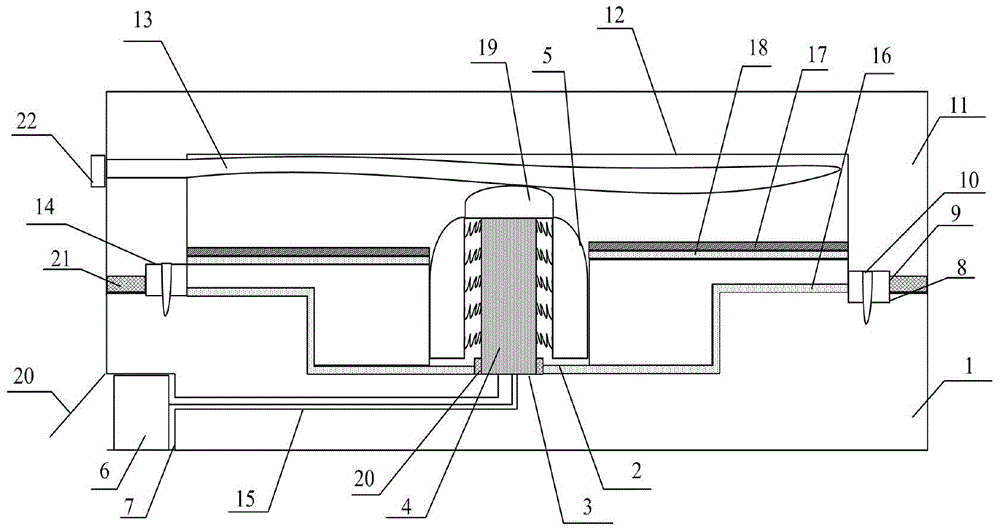
[0047] figure 1 It shows an implementation form of a new tool box according to the present invention, which is used to accommodate a milling cutter with a shaft insertion hole in the middle, and the shaft insertion hole is set in the center of the milling cutter head, including:

[0048] The box body 1 is in the shape of a regular cuboid and only an opening 2 is reserved at the top, and the middle part of the opening is provided with a fixing column 3 higher than the top of the box body, and the fixing column and the bottom of the box body are detachable At the same time, the fix...


PUM


Abstract

The invention discloses a novel tool box which comprises a box body and a cover body. A fixing column higher than the top of the box body is arranged in the middle of the box body. An electromagnet is arranged in the fixing column. A first containing cavity for containing a storage battery is formed in one side face of the box body by the fact that the side face is concave inwards. The cover body is connected to one side of the box body in a pivoting mode. A second containing cavity capable of containing a milling cutter disc is arranged in the cover body. An air bag is arranged in the second containing cavity. A lead groove is formed between the first containing cavity and an opening. A power supply wire of the electromagnet penetrates through the lead groove and is connected with the storage battery. The air bag is used for sealing a gap between the second containing cavity of the cover body and the milling cutter disc to stabilize a milling cutter arranged in the tool box. The tool box has the advantages of being high in applicability, good in stability, light in weight and convenient to convey. The invention further provides a manufacturing and using method of the novel tool box.

Description

technical field [0001] The invention relates to a plastic knife case used in the case of storing knives. More specifically, the present invention relates to a novel tool case and methods of making and using it for storage and transport of milling cutters. Background technique [0002] Existing milling cutters used in industrial production are mainly stored in metal tool boxes when they are used for storage or transportation. [0003] Specifically, it generally includes the following structures: a box body, which has an accommodating cavity matching the external shape of the milling cutter, and a cover body, which is closed to seal the milling cutter located in the box body. [0004] However, in this structure, because the components only use the cover to close the milling pair, the stability of the milling cutter cannot be controlled, and because of the housing inside the box that matches the external shape of the specific milling cutter As a result, the tool box can only ...

Claims


Application Information

Patent Timeline
Patent Type & Authority Patents(China)
IPC IPC(8): B23Q13/00B25H3/02
CPCB23Q13/00B25H3/02
Inventor 张清和张文昊
Owner 绵阳宏信塑胶制品有限公司
Learn More