
Automatic processing machine tool for bended tubes

A technology of automatic processing and machine tools, which is applied in the direction of metal processing machinery parts, metal processing, metal processing equipment, etc., can solve the problems of low processing efficiency and unguaranteed processing accuracy, and achieve the effect of improving processing efficiency and realizing processing automation

Inactive Publication Date: 2015-05-20
刘永伟
View PDF0 Cites 4 Cited by
  • Summary
  • Abstract
  • Description
  • Claims
  • Application Information

AI Technical Summary

Problems solved by technology

[0002] The welded elbow is made of a forged pipe and then the groove is processed to ensure the welding quality. The groove of the existing pipe bend is clamped by the machine tool, aligned, and then cut by the turning tool. During the processing, due to The processing surface needs to be reversed and turned to find the center, the processing efficiency is extremely low, and the processing accuracy cannot be guaranteed

Method used


Image

  • Automatic processing machine tool for bended tubes
  • Automatic processing machine tool for bended tubes
  • Automatic processing machine tool for bended tubes

Examples


Embodiment 1

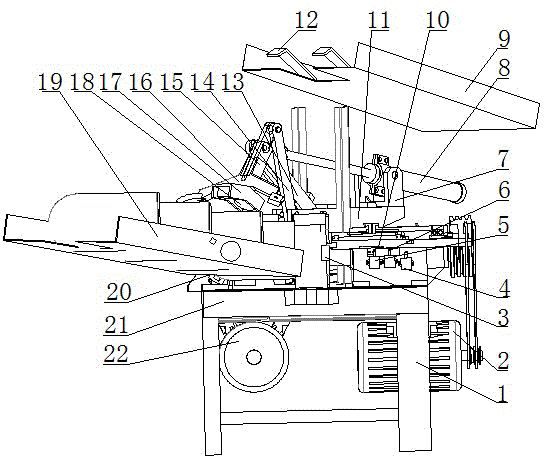
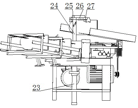
[0014] Such as figure 1 with image 3 As shown, the structure of the pipe bending automatic processing machine tool is as follows: the upper end of the frame body 1 is provided with a rectangular platform 21, and the lower end of the platform 21 corresponds to the pulley of the milling cutter head. The belt pulley is connected to the pulley of the milling cutter head 3. The two adjacent right-angled sides of the upper end of the platform 21 are respectively provided with the milling cutter head 3. The milling cutter head 3 is connected to the sleeve. The included angle of the axis can be set to 120 respectively according to the needs 0 、90 0 、45 0 , the upper end of the milling cutter head 3 sides is equipped with a slide block 10, the side end of the milling cutter head 3 is provided with a vertical plate perpendicular to the platform 21, and the vertical plate is respectively provided with a travel switch one 4, a travel switch two 5 and a travel switch three 6, The plat...

Embodiment 2

[0016] The structure of the pipe bending automatic processing machine tool is as follows: the upper end of the frame body 1 is provided with a rectangular platform 21, and the lower end of the platform 21 corresponds to the pulley of the milling cutter head. The pulley of the cutter head 3, the two adjacent right-angled sides of the upper end of the platform 21 are respectively provided with the milling cutter head 3, the milling cutter head 3 is connected to the sleeve, and the side end of the sleeve is equipped with a screw nut device, and the angle between the two milling cutter heads 3 axes According to needs can be set to: 120 0 、90 0 、45 0 , the upper end of the milling cutter head 3 sides is equipped with a slide block 10, the side end of the milling cutter head 3 is provided with a vertical plate perpendicular to the platform 21, and the vertical plate is respectively provided with a travel switch one 4, a travel switch two 5 and a travel switch three 6, The platform...


PUM


Abstract

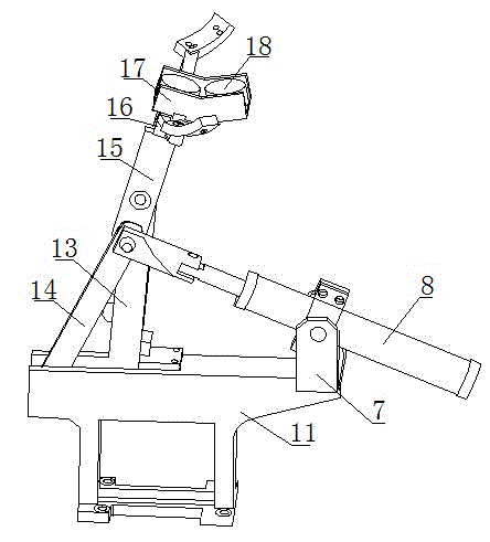
The invention discloses an automatic processing machine tool for bended tubes and belongs to the technical field of machining equipment. A rectangular platform is arranged at the upper end of a frame body, a motor I and a motor II, corresponding to belt pulleys of milling heads, are respectively mounted at the lower end of the platform, and are connected with the belt pulleys of the milling heads through belt pulleys; milling heads are arranged at two adjacent right-angle sides at the upper end of the platform, respectively; the milling heads are connected with a sleeve, a lead screw device is mounted at the side end of the sleeve, the axis angles of the two milling heads can be respectively set as 1200, 900 and 450 degrees according to demand, a slide block is arranged at the upper end of the side of each milling head, a feeding channel is arranged on the platform at the right-angled end of each of the milling heads, and a hydraulic clamp is arranged between the two milling heads; an overturning device and a material receiving groove are structured in that the middle of the platform is hinged with the lower ends of a main supporting rod and an auxiliary supporting rod, the upper end of the main supporting plate is hinged to the middle of an upper rotating rod and the front end of a transverse oil cylinder at the same time, the upper end of the auxiliary supporting rod is hinged with the rear end of the upper rotating rod, the front end of the upper rotating rod is connected with the rear end of a fork-shaped connecting rod, the front end of the fork-shaped connecting rod is connected with a magnet seat, and two electromagnets I are respectively mounted on the magnet seat.

Description

technical field [0001] The invention relates to a pipe bending automatic processing machine tool, which belongs to the technical field of mechanical processing equipment. Background technique [0002] The welded elbow is made of a forged pipe and then the groove is processed to ensure the welding quality. The groove of the existing pipe bend is clamped by the machine tool, aligned, and then cut by the turning tool. During the processing, due to The processing surface needs to be reversed and turned to find the center, the processing efficiency is extremely low, and the processing accuracy cannot be guaranteed. Contents of the invention [0003] In order to overcome the above-mentioned technical deficiencies, the present invention provides an automatic pipe bending machine tool, which can automatically clamp the pipe for cutting and processing, and can automatically put the processed pipe into the tray after processing middle. [0004] The technical solution adopted by th...

Claims


Application Information

Patent Timeline
Patent Type & Authority Applications(China)
IPC IPC(8): B23C3/00B23Q7/00B23Q5/10
CPCB23C3/00B23Q7/00
Inventor 刘永伟张爱民刘博非
Owner 刘永伟
Learn More