Assembly structure of induction magnetic ring and shaft of motor rotor

A technology of induction magnetic ring and assembly structure, applied in the direction of electromechanical devices, electrical components, etc., can solve problems such as uneven distribution of magnetic force lines of induction magnetic ring, induction failure of Hall sensor, displacement or rupture of induction magnetic ring, etc., and achieve product stability Good performance, solve the problem of pressing and matching, and ensure the effect of product quality

Active Publication Date: 2016-11-23
YUYAO ACTUATOR ELECTRIC MOTOR CO LTD
View PDF9 Cites 0 Cited by
  • Summary
  • Abstract
  • Description
  • Claims
  • Application Information

AI Technical Summary

Problems solved by technology

[0006] The purpose of the present invention is to aim at the prior art of the above-mentioned permanent magnet brushless DC motor, in the process of assembling and using the whole machine, the induction magnetic ring is prone to displacement or rupture, which will cause uneven distribution of the magnetic force lines of the induction magnetic ring and small magnetic flux The problem is that the hall sensor will fail to sense and the motor will fail. An assembly structure of the induction magnetic ring and the rotating shaft of the motor rotor is provided, which can achieve that the induction magnetic ring does not shift during assembly and use of the whole machine. , no cracking, can solve the problem of uneven distribution of magnetic force lines of the induction magnetic ring and small magnetic flux, and can also make the Hall sensor induction not fail, and the motor can run normally

Method used


Image

  • Assembly structure of induction magnetic ring and shaft of motor rotor
  • Assembly structure of induction magnetic ring and shaft of motor rotor
  • Assembly structure of induction magnetic ring and shaft of motor rotor

Examples


Embodiment Construction

[0026] The present invention will be further described below in conjunction with the accompanying drawings and specific embodiments, but not as a limitation of the present invention.

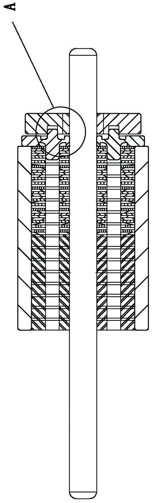
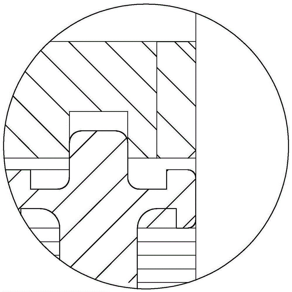
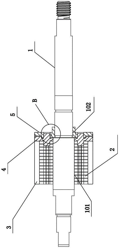
[0027] Such as Figure 2-1 to Figure 3-3 As shown, the assembly structure of the induction magnetic ring and the rotating shaft of the motor rotor, the motor is a permanent magnet brushless DC motor, and the assembly structure of the induction magnetic ring and the rotating shaft of the permanent magnet brushless DC motor rotor includes a stepped mode rotating shaft 1, a rotor iron Core 2, main magnet 3, plastic bushing 4 and induction magnetic ring 5.

[0028] The stepped mode shaft 1 includes a piercing portion A 101 and a piercing portion B 102, the rotor core 2 and the plastic bushing 4 are pierced on the piercing portion A 101 of the stepped mode shaft 1, and the induction magnetic ring 5 is threaded on the piercing part B 102 of the step mode rotating shaft 1; the plastic bushing 4 is arr...


PUM


Abstract

The invention discloses an assembling structure for a sensing magnetic ring and a rotating shaft of a motor rotor, and belongs to the technical field of motor parts. The assembling structure comprises a step-mode rotating shaft, a rotor iron core, a main magnet body, a plastic bushing and a sensing magnetic ring, wherein the step-mode rotating shaft comprises a penetrating part A and a penetrating part B; the sensing magnetic ring comprises a sensing magnetic ring main body and a step-mode liner copper sleeve; the sensing magnetic ring main body and the step-mode liner copper sleeve are in inlaid close-fitting connection; the main magnet body is arranged outside the rotor iron core in a sleeving manner and is in adhesive connection with the rotor iron core; an annular step end surface A is arranged between the penetrating part A and the penetrating part B of the step-mode rotating shaft; an annular step end surface B is arranged in a central hole of the step-mode liner copper sleeve; a rotating shaft pressing fit section is arranged on the right side of the annular step end surface B; an avoiding gap is formed in the left side of the annular step end surface B; the length of the avoiding gap is greater than that of the matching section of the sensing magnetic ring main body. The assembling structure has the benefits that the sensing magnetic ring does not move and crack; the problems that sensing magnetic ring magnetic lines are distributed unevenly and the magnetic flux is low can be solved; the sensing of a Hall sensor does not fail; a motor can operate normally.

Description

technical field [0001] This product is an assembly structure of a motor rotor, especially relates to an assembly structure of an induction magnetic ring and a rotating shaft of a motor rotor, and belongs to the technical field of motor components. Background technique [0002] The permanent magnet brushless DC motor not only has the advantages of high efficiency, good starting performance and good speed regulation performance of the commonly used DC brush, but also has the characteristics of long life, high reliability, low noise, and can be used in explosion-proof occasions. In actual production , is widely used. [0003] However, in conventional permanent magnet brushless DC motors, the position accuracy of the induction magnetic ring cannot be guaranteed. Such as Picture 1-1 ,Such as Figure 1-2 As shown, the round optical axis is closely matched with the induction magnetic ring, and the position of the induction magnetic ring is controlled by the mold fixture. There ...

Claims


Application Information

Patent Timeline
Patent Type & Authority Patents(China)
IPC IPC(8): H02K29/06
Inventor 冯豪士
Owner YUYAO ACTUATOR ELECTRIC MOTOR CO LTD
Why Eureka
Try Eureka