
CMOS reference current and reference voltage generating circuit

A technology for generating circuits and reference currents, applied in the direction of adjusting electrical variables, instruments, control/regulating systems, etc., and can solve problems such as large power supply voltage adjustment rates

Inactive Publication Date: 2015-05-13
HUAZHONG UNIV OF SCI & TECH
View PDF5 Cites 10 Cited by
  • Summary
  • Abstract
  • Description
  • Claims
  • Application Information

AI Technical Summary

Problems solved by technology

In this case, the groove length modulation effect is ignored, the actual current obtained is affected by the power supply, and the power supply voltage adjustment rate is relatively large

Method used


Image

  • CMOS reference current and reference voltage generating circuit
  • CMOS reference current and reference voltage generating circuit
  • CMOS reference current and reference voltage generating circuit

Examples


Embodiment Construction

[0026] In order to make the object, technical solution and advantages of the present invention clearer, the present invention will be further described in detail below in conjunction with the accompanying drawings and embodiments. It should be understood that the specific embodiments described here are only used to explain the present invention, not to limit the present invention. In addition, the technical features involved in the various embodiments of the present invention described below can be combined with each other as long as they do not constitute a conflict with each other.

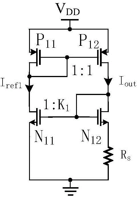
[0027] The present invention is improved on the basis of the traditional current source circuit, the traditional basic current source circuit such as figure 1 shown. PMOS tube P 11 with P 12 form a pair of current mirror structures, and P 11 and P 12 have the same dimensions, so that the current I ref1 and I out equal. Due to the resistor R s The role of NMOS tube N 11 and N 12 The ga...


PUM


Abstract

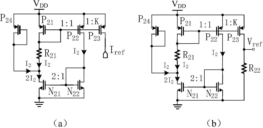
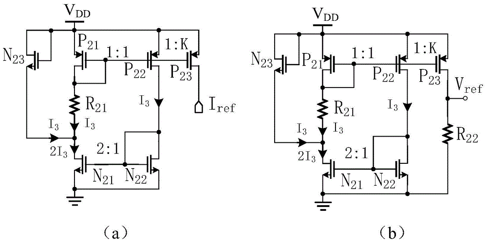
The invention discloses a CMOS reference current and reference voltage generating circuit. Two MOS pipes working in a saturation region are built, the current across the two MOS pipes is made to be equal and is obtained through the absolute value difference of the gate source voltage of the two MOS pipes, and the current is utilized to generate reference current or reference voltage. When the conduction types of the two MOS pipes are the same, the absolute value difference of the gate source voltage is converted to the absolute value difference of the threshold voltage of the MOS pipes by adjusting the size of the MOS pipes. When the conduction types of the two MOS pipes are opposite to each other, the differential coefficient of the output reference voltage to the temperature is made to be zero by adjusting the size of the MOS pipes. By means of the CMOS reference current and reference voltage generating circuit, the influences on the reference voltage of the temperature can be effectively eliminated, so that the temperature drift factor of the reference voltage is greatly lowered, and influences, on the reference current and the reference voltage, of the power source voltage and a process can be lowered to the maximum degree; furthermore, the circuit is a pure CMOS circuit, the power consumption of the circuit is lower, and the area of a chip is lowered obviously compared with a traditional bandgap reference source.

Description

technical field [0001] The invention belongs to the technical field of analog integrated circuits, and more specifically relates to a CMOS reference current and reference voltage generating circuit. Background technique [0002] Reference voltage source and reference current source are an important unit module in many analog and digital-analog hybrid integrated circuits, and are widely used in circuits such as energy converters, analog-to-digital converters, and low-dropout linear regulators. With the continuous shrinking of integrated circuit chip size and continuous improvement of performance, the design of high-precision, low-voltage, low-power, high-performance voltage reference source and reference current source has become a focus of attention in the field of integrated circuits. [0003] The traditional most commonly used reference voltage source is a bandgap reference source, and its basic design idea is: use the voltage difference V between the base and the emitter ...

Claims


Application Information

Patent Timeline
IPC IPC(8): G05F1/56
Inventor 邹志革孙帆雷鑑铭邹雪城蔡湧达
Owner HUAZHONG UNIV OF SCI & TECH
Learn More