Tube-and-shell heat exchanger

A shell-and-tube heat exchanger, heat exchanger technology, applied in the direction of heat exchanger type, heat exchanger shell, indirect heat exchanger, etc. damage and other problems, to avoid adhesion and aggregation, ensure smooth circulation, and avoid smoothness.

Active Publication Date: 2015-05-13
枣庄科顺数码有限公司
View PDF6 Cites 0 Cited by
  • Summary
  • Abstract
  • Description
  • Claims
  • Application Information

AI Technical Summary

Problems solved by technology

[0004] Although the current tube-and-tube heat exchanger can achieve heat exchange function well, in practical applications, there is often a situation where the temperature difference between the shell wall and the tube wall is large (caused by factors such as the large temperature difference between the two liquids), As a result, the thermal elongation of the shell and the heat exchange tube is significantly different, which will cause a considerable temperature difference stress between the shell and the heat exchange tube and the extrusion destructive force between the structures, resulting in serious damage to the equipment

Method used


Image

  • Tube-and-shell heat exchanger
  • Tube-and-shell heat exchanger
  • Tube-and-shell heat exchanger

Examples


Embodiment Construction

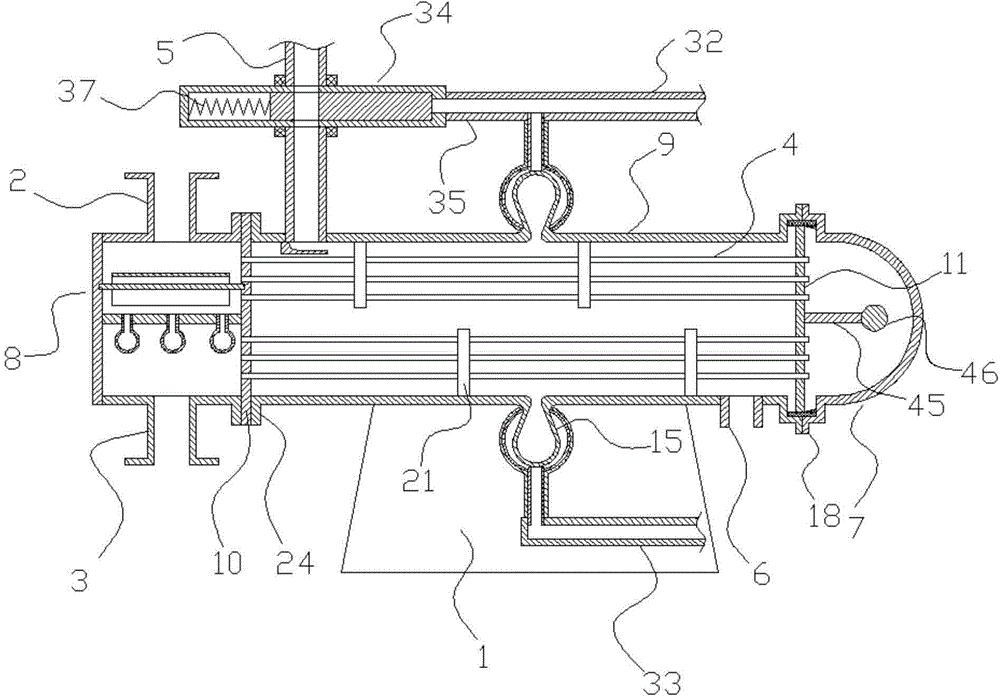
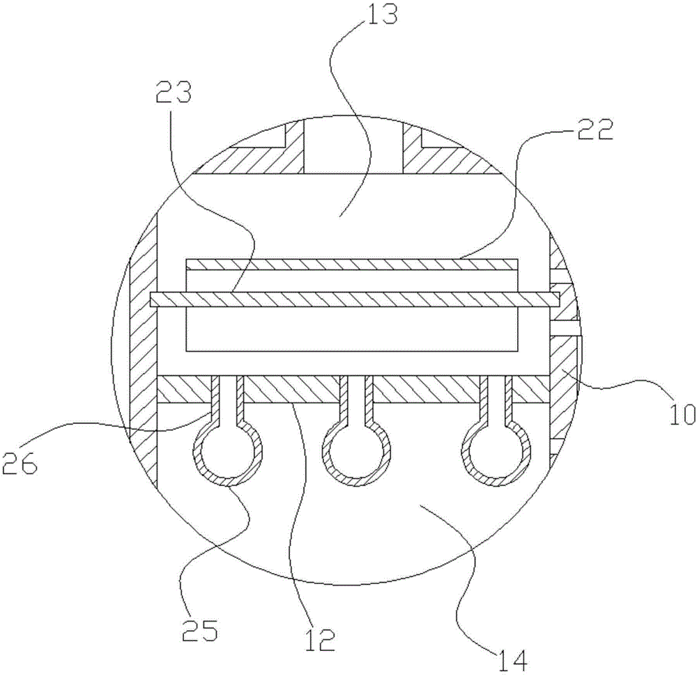
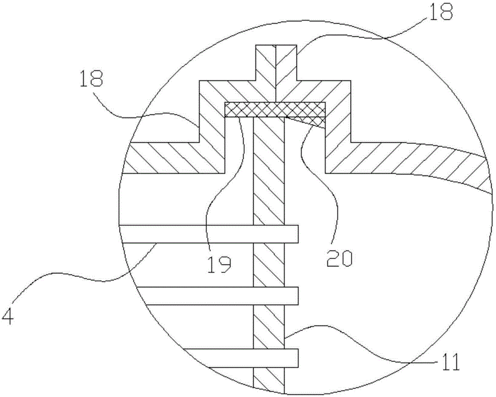
[0026] The present invention will be further described below in conjunction with the drawings and specific embodiments.

[0027] Such as figure 1 , figure 2 , image 3 , Figure 4 , Figure 5 , Image 6 , Figure 7 , Figure 8 In the illustrated embodiment, a shell-and-tube heat exchanger includes a tube-side part, a shell-side part, and a number of brackets 1. The tube-side part includes a tube-side inlet tube 2, a tube-side outlet tube 3, and a plurality of The heat exchange tube 4, the shell side part includes a transverse heat exchanger outer shell, a shell side inlet tube 5, and a shell side outlet tube 6. The heat exchanger outer shell consists of a sealing head 7, a shell head 8, A tube box 9 with openings at both ends is formed together, a fixed tube plate 10 is provided between the shell head and the tube box, and a head tube plate 11 is provided between the head and the tube box. The two ends of the heat exchange tube are respectively connected to the fixed tube plate...


PUM


Abstract

The invention discloses a tube-and-shell heat exchanger and aims to provide a heat exchanger, allowing effective heat exchange between two liquids, having thermal difference compensating capacity and preventing damage caused by thermal difference stress between a shell and heat exchange tubes. The tube-and-shell heat exchanger comprises a tube side portion, a shell side portion and a plurality of supports; the tube side portion comprises a tube side incoming tube, a tube side outgoing tube and a plurality of heat exchange tubes; the shell side portion comprises a housing, a shell side incoming tube and a shell side outgoing tube; the housing is composed of a seal head, a shell head and a tube box; a fixing tube plate is disposed between the shell head and the tube box; a seal head tube plate is disposed between the seal head and the tube box; a tube side partition plate divides the inside of the shell head into a tube side inflow cavity and a tube side outflow cavity; the tube box is provided with an expansion joint. The tube-and-shell heat exchanger has the advantages that the expansion joint featuring ease of deformation and the seal head tube plate slidable fit to function in structural thermal difference compensation, and structural damage caused by excessively high thermal temperature stress is avoided.

Description

Technical field [0001] The invention belongs to the technical field of chemical heat exchange, and particularly relates to a shell-and-tube heat exchanger. Background technique [0002] Heat exchangers are process equipment for heat transfer, which are widely used in oil refining, petrochemical industries and other general chemical industries. Examples include cooling, condensation, heating, evaporation and waste heat recovery. Due to the variety of use conditions (corrosiveness, temperature, pressure, medium, impurities, heat exchange capacity, etc.), the heat exchanger also needs to have a reasonable structure and form. [0003] Tubular heat exchanger (shell and tube heat exchanger) is one of the most widely used heat transfer equipment at present. It exchanges heat between two liquids in the following way: one liquid flows through the shell and outside the heat exchange tube , Another liquid flows through the heat exchange tube, and the heat exchange tube performs heat exchang...

Claims


Application Information

Patent Timeline
Patent Type & Authority Applications(China)
IPC IPC(8): F28D7/16F28F9/02F28F13/12
Inventor 卢晓丽
Owner 枣庄科顺数码有限公司
Why Eureka
Try Eureka