Improving pulverized coal ignition combustion w flame boiler
A staged combustion and pulverized coal technology, which is applied to the combustion of block fuel and powder fuel, the combustion of liquid fuel and powder fuel, the combustion of gaseous fuel and powder fuel, etc. It can solve the problem of late ignition of pulverized coal jet, Thermal fatigue cracking of the water wall of the cold ash hopper, slagging of the front and rear walls, etc., to improve combustion stability and burnout rate, improve the slagging of the front and rear walls, and improve the effect of timely supplementary oxygen combustion
- Summary
- Abstract
- Description
- Claims
- Application Information
AI Technical Summary
Problems solved by technology
Method used
Image

Examples
Embodiment 1
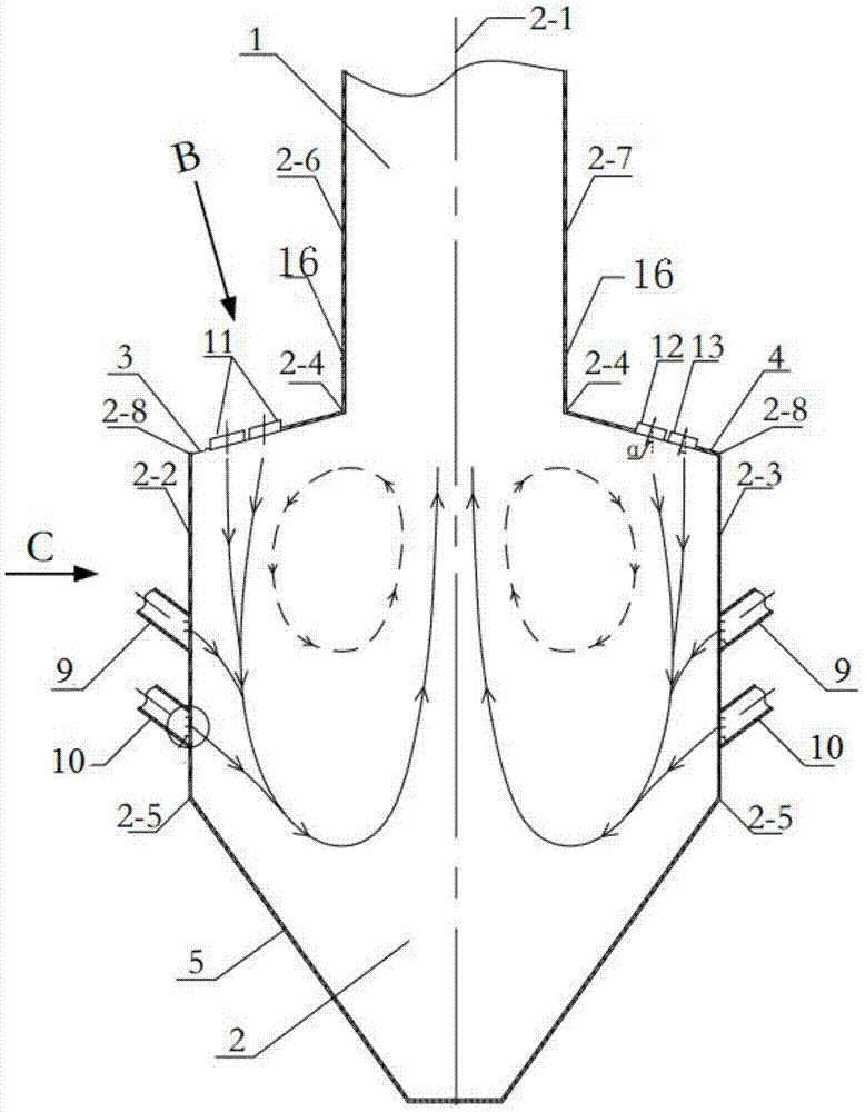
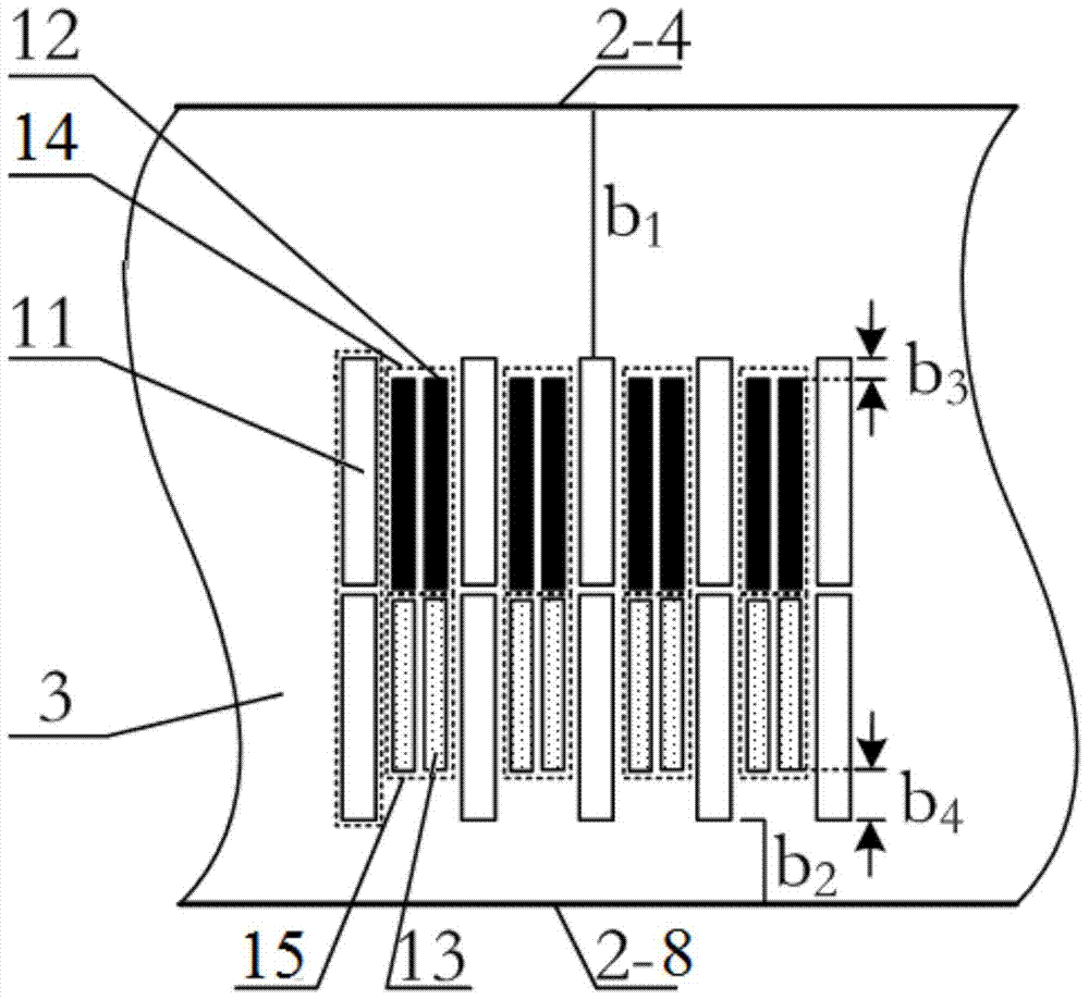
[0029] Embodiment 1: as Figures 1 to 3 As shown, a kind of injection staged combustion W-flame boiler for improving pulverized coal ignition and combustion described in this embodiment 1 includes a furnace consisting of an upper furnace 1, a lower furnace 2, a front furnace arch 3 and a rear furnace arch 4. The front furnace arch 3 is set between the furnace center 2-1 and the furnace front wall water-cooled wall 2-2, and the rear furnace arch 4 is set between the furnace center 2-1 and the furnace rear wall water-cooled wall 2-3 A plurality of secondary air nozzles, a plurality of pulverized coal airflow nozzles, the plurality of secondary air nozzles and a plurality of pulverized coal airflow nozzles are all connected to the lower furnace 2, and the plurality of secondary air nozzles include a plurality of secondary airflow nozzles. Wind spout group 6, each secondary air spout group 6 is made up of two secondary air spouts 11 arranged close to each other before and after; t...
Embodiment 2
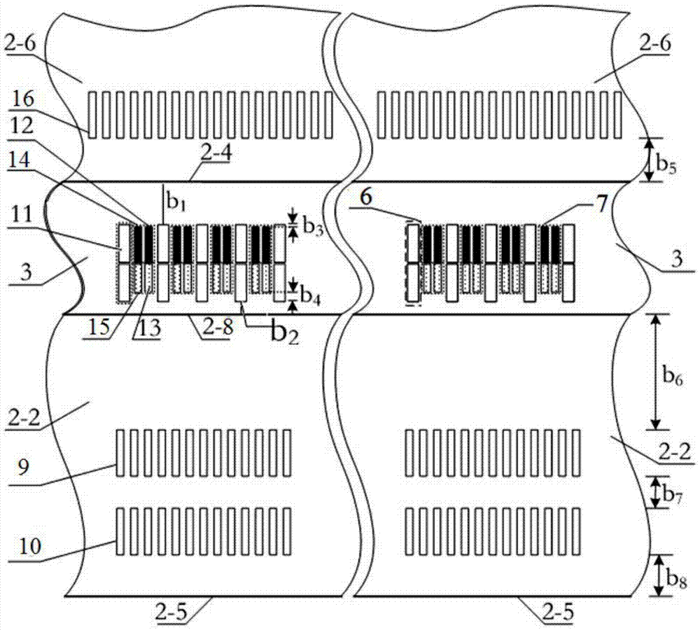
[0030] Embodiment 2: as Figure 1 to Figure 3 As shown, the difference between the ejection staged combustion W flame boiler described in Embodiment 2 and Embodiment 1 for improving pulverized coal ignition and combustion is that the front wall water cooling wall 2-6 and the rear wall water cooling wall of the upper furnace 1 2-7 is provided with a plurality of overburning air nozzles 16, and the said overburning air nozzles 16 are arranged side by side in a straight line along the width direction of the furnace. The distance between boundary line 2-4 is b 5 , b 5 If it is greater than zero, the water cooling wall 2-2 of the front wall and the water cooling wall 2-3 of the rear wall of the furnace are symmetrically arranged with the upper layer tertiary air nozzle 9 and the lower layer tertiary air nozzle 10, and the upper layer tertiary air nozzle 9 and the lower layer tertiary air nozzle 10 are along the furnace width direction Arranged side by side at equal intervals in a...
Embodiment 3
[0031] Embodiment 3: as Figure 1 to Figure 6 As shown, the difference between Embodiment 3 and Embodiment 2 is that a plurality of pulverized coal gas flow nozzle groups 7 are fixedly installed at a certain angle to the center of the furnace, and the angle between the installation angle and the center line is α, and the value range of α is 5 to 10°, multiple secondary air nozzle groups 6 are provided with a secondary air angle adjustment mechanism, the secondary air angle adjustment mechanism includes a stepping motor 35, a coupling 32, a gearbox 33, a multi-stage cylindrical straight The gear 34, the secondary air nozzle 11 is fixed in the secondary air box through the bearing 31, the secondary air nozzle group 6 is connected with the multi-stage spur gear 34, and the multi-stage spur gear 34 is arranged in the gearbox 33, and the speed change The box 33 is connected with the stepper motor 35 through a coupling 32, a gap is provided between the secondary air nozzle 11 and th...
PUM
 Abstract
Description
Claims
Application Information
 - R&D
- Intellectual Property
- Life Sciences
- Materials
- Tech Scout
- Unparalleled Data Quality
- Higher Quality Content
- 60% Fewer Hallucinations
Browse by: Latest US Patents, China's latest patents, Technical Efficacy Thesaurus, Application Domain, Technology Topic, Popular Technical Reports.
© 2025 PatSnap. All rights reserved.Legal|Privacy policy|Modern Slavery Act Transparency Statement|Sitemap|About US| Contact US: help@patsnap.com